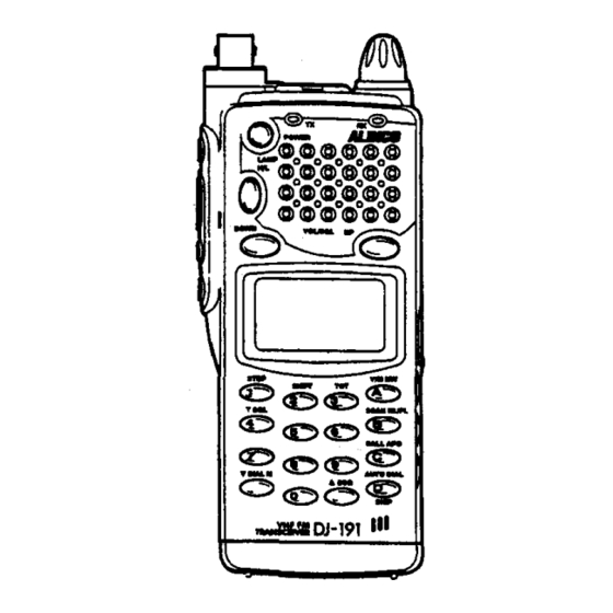
Alinco DJ-191 Instrukcja obsługi - Strona 4
Przeglądaj online lub pobierz pdf Instrukcja obsługi dla Odbiornik Alinco DJ-191. Alinco DJ-191 18 stron. Cert communications team procedures
Również dla Alinco DJ-191: Instrukcja obsługi (18 strony), Skrócona instrukcja obsługi (3 strony), Skrócona instrukcja obsługi (4 strony)

III
III
3-2 Optional Accessories
4-1 Mobile Installation
External Antenna Installation (Not applicable for DJ-491 C):
When an external antenna is used, 50 ohms coaxial cable is required for all antenna
installations.
Please refer to the antenna manufacturer's manual for the proper installation and
mounting information. After installing your antenna, ensure that you have the proper
matching and best possible SWR reading. High SWR or improper matching can cause
severe damage to your unit and may void the warranty.
(Note: When your DJ-191 is used with an external antenna, you may experience some
intermodulation problem from other communication services. This is caused due to the
high sensitivity of the DJ-191 's receiver front-end circuit and its design for wideband
operation. If it is the case, we recommend you to use an antenna that has a lower gain
or the rubber duckie antenna which comes standard with the radio.)
4. INSTALLATION
for DC Power Supply
Ee--@-e
2. Power Requirements
The transceiver can be operated from
any regulated 12 or 13.8V DC negative
ground source.
For mobile use, use always with the
optional EDC-36 cigarette lighter adap-
ter with active noise filter.
t
ffi
~e
For a fixed base operation, 4.8V DC -13.8V DC RegUlated Power Supply providing a
minimum of 2A continuous is required.
When using the optional EDC-37 DC cable, connect the red lead of to the Positive (
+)
terminal, and the black lead to the Negative (-) terminal of the DC Power Supply.
4·2 Base Station Installation
4-3 Charging Your Battery
Before operating your transceiver, you must charge your Ni-ed battery with the wall
charger that comes standard with your radio.
It will take approx. 12 to 14 hours to
be
fUlly charged.
1. Location
The transceiver may be installed in any
position· in your car, where the controls
are easily accessible while maintaining
safe operation of your vehicle.
(·Iocal regulations may apply)
III
CTCSS Decoder Unit
(4.8V DC 650mAH) Ni-ed battery
(4.8V DC 1200mAH) Ni-ed battery
(7.2V DC 9OOmAH) Ni-ed battery
(9.6V DC 650mAH) Ni-ed battery
(4.8V DC 700mAH) Ni-ed battery
Dry-cell battery case
(AA x
4)
Mobile Cigarette lighter adapter with active noise filter
External DC supply cable
(120V AC) Rapid charger
(220V AC) Rapid charger
(120V AC) Wall charger
(220V AC) Wall charger
Speaker microphone
Headset with VOX
Earphone and mic with VOX
Earphone
Softcase (for use with EBP-33N)
Softcase (for use with EBP-37N)
Softcase (for use with EBP-34N/35N/36N)
Mobile bracket
SmarTrunk™ Logic Board (for commercial versions only)
EJ-28U
EBP-33N
EBP-34N
EBP-35N
EBP-38N
EBP-37N
EDH-16
EDC-36
EDC-37
EDC-60
EDC-81
EDC-83
EDC-64
EM8-9
EME-12
EME-13
EME-6
ESC-28
ESC-29
ESC-30
EBC-6
EJ-27D
2
caution: High RF environments can cause severe damage to your unit. Ensure that
you are not in a High RF environment when operating your radio.
3
