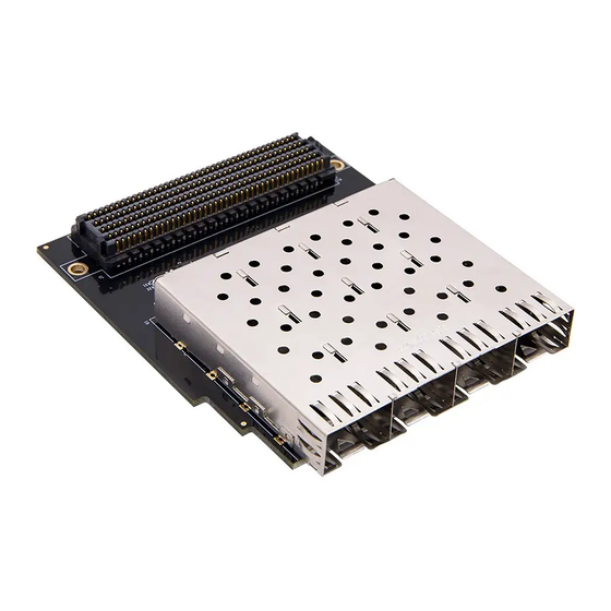
Alinx FH1223 Podręcznik użytkownika - Strona 5
Przeglądaj online lub pobierz pdf Podręcznik użytkownika dla Jednostka sterująca Alinx FH1223. Alinx FH1223 10 stron. Fmc to 4 spf module

Part 2: FH1223 Module Function Description
Part 2.1: FH1223 Module Block Diagram
Figure 2-1: FH1223 Module Block Diagram as below:
Part 2.2: FMC LPC Module Pin Assignment
Only the power and interface signals are listed below, and the GND signal
is not listed. Users can refer to the schematic diagram.
FMC Pin
Number
A2
A3
A6
A7
A10
A11
A14
A15
A18
A19
A22
A23
5 / 10
FMC to 4* SFP Module FH1223 User Manual
Figure 2-1: FH1223 Module Block Diagram
Network Name
SFP2_RX_P
SFP2_RX_N
SFP3_RX_P
SFP3_RX_N
SFP4_RX_P
SFP4_RX_N
FMC_DP4_M2C_P
FMC_DP4_M2C_N
FMC_DP5_M2C_P
FMC_DP5_M2C_N
SFP2_TX_P
SFP2_TX_N
Description
The 2
SFP Signal, Receive Positive
nd
The 2
SFP Signal, Receive Negative
nd
The 3
rd
SFP Signal, Receive Positive
The 3
rd
SFP Signal, Receive Negative
The 4
SFP Signal, Receive Positive
th
The 4
SFP Signal, Receive Negative
th
Not Used
Not Used
Not Used
Not Used
The 2
nd
SFP Signal, Transmit Positive
The 2
nd
SFP Signal, Transmit Negative
www.alinx.com
