Garmin GMA 340 Instrukcja instalacji - Strona 18
Przeglądaj online lub pobierz pdf Instrukcja instalacji dla Wyświetlacz awioniki Garmin GMA 340. Garmin GMA 340 43 stron. Audio panel
Również dla Garmin GMA 340: Podręcznik pilota (12 strony), Dodatkowa instrukcja obsługi (10 strony), Podręcznik pilota (4 strony), Podręcznik pilota (8 strony), Podręcznik pilota (8 strony), Podręcznik pilota (12 strony)

2.5.3
Noise
Because the audio panel is a point in the aircraft where signals from many pieces of equipment are brought
together, care must be taken to minimize effects from coupled interference and ground loops.
Coupled interference can sneak into audio system interconnecting cables when they are routed near large AC
electric fields, AC voltage sources, and pulse equipment (strobes, spark plugs, magnetos, EL displays, CRTs, etc).
Interference can also couple into audio system interconnecting cables by magnetic induction when they are routed
near large AC current-carrying conductors or switched DC equipment (heaters, solenoids, fans, autopilot servos,
etc).
Ground loops are created when there is more than one path in which return currents can flow, or when signal
returns share the same path as large currents from other equipment. These large currents create differences in
ground potential between the various equipment operating in the aircraft. These differences in potential can
produce an additive effect at an audio panel signal input.
The audio panel may "see" the desired input signal plus an unwanted component injected by ground differentials,
a common cause of alternator-related noise. This is the main reason why all audio jacks should be isolated from
ground. Terminating audio shields just at one end eliminates another potential ground loop injection point.
Single-point grounding cannot be overstressed for the various avionics producing and processing audio signals.
Single-point, in this context, means that the various pieces of equipment share a single common ground
connection back to the airframe. Good aircraft electrical/charging system ground bonding is also important.
The wiring diagrams and accompanying notes in this manual should be followed closely to minimize noise
effects.
2.6
POST INSTALLATION CHECKOUT
Check wiring connections for errors before inserting the GMA 340 into the tray.
Incorrect wiring could cause internal component damage.
Except for marker beacon operation, an in-aircraft checkout may be performed in the aircraft on the ramp with
known good microphone, headset, speaker and avionics receivers. Item numbers in parentheses refer to front
panel controls shown in figure 3-1, page 3-1.
2.6.1
Lamp Test
Apply power to the unit by rotating the pilot intercom knob (5) clockwise.
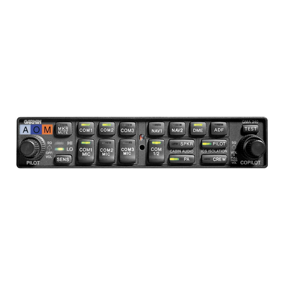
The GMA 340 test button (17) checks the internal LED annunciators and marker beacon LEDs (1). Press TEST
to confirm operation of the LEDs. Cover the photocell (19) with a finger and observe that the LED annunciators
dim automatically. Check the front panel backlighting and dimming function. Each annunciation is illuminated.
Page 2-6
Rev. L
CAUTION
GMA 340 Installation Manual
190-00149-01
