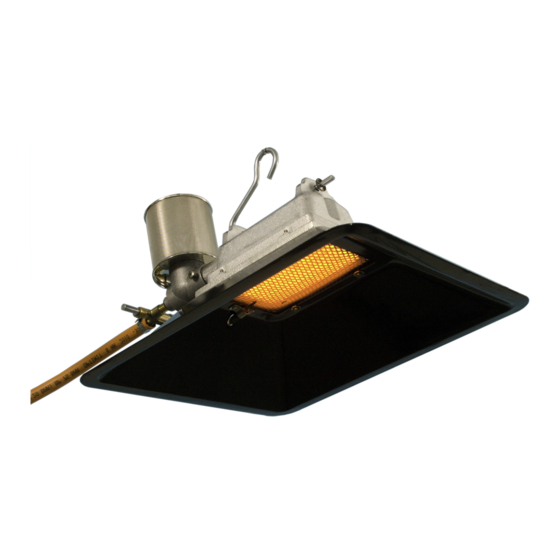
Alke 41-FT Instrukcja obsługi, serwisu i instalacji - Strona 12
Przeglądaj online lub pobierz pdf Instrukcja obsługi, serwisu i instalacji dla Grzałka Alke 41-FT. Alke 41-FT 13 stron. Atmospheric ceramic luminous infra-red heaters for use in well ventilated areas

Technical table
Category
Gas
Maximum
Supply
pressure
(-)
(-)
(mbar)
41 series
I2L
G25
25
I2EK (K)
G25.3 25
I2H, I2E, I2E+
G20
20
I2ELL (LL)
G25
50
I2ELL (E)
G20
50
I3P
G31
28
I3P
G31
50
I3P
G31
150
I3P
G31
200
I3P
G31
1400
61 series
I2L
G25
25
I2EK (K)
G25.3 25
I2ELL (LL)
G25
50
I2ELL (E)
G20
50
I3P
G31
50
I3P
G31
150
I3P
G31
1400
81 series
I2EK (K)
G25.3 25
I2H, I2E, I2E+
G20
20
I2ELL (LL)
G25
50
I2ELL (E)
G20
50
I3P
G31
30
I3P
G31
50
I3P
G31
150
I3P
G31
200
I3P
G31
1400
** In case the heater is equipped with a thermostat (T) with bypass injector the heater shall be operated on maximum supply pressure only. See also the pressure information on the data plate
Conversion calculation from gross heat input kW(Hs) to nett heat input kW(Hi):
Propane: divide gross heat input kW(Hs) by factor 1,09 (example: 1,20 kW(Hs) / 1,09 = 1,10 kW(Hi)
Natural gas: divide gross heat input kW(Hs) by factor 1,11 (example: 1,20 kW(Hs) / 1,11 = 1,08 kW(Hi)
G31 = propane; G20 = natural gas (100% methane); G25 = natural gas (86% methane); G25.3 = natural gas (88% methane); Biogas = 60% methane + 40% carbon dioxide
Version 1.0: March 2018
Minimum
Max.
Min.
Supply
Heat
Heat
pressure **
Input
Input
(mbar)
(kW Hs)
(kW Hs)
x
2,0
x
x
2,05
x
x
1,8
x
25
1,9
1,35
25
1,9
1,35
x
1,5
x
x
1,65
x
50
1,60
0,90
50
1,85
0,90
500
1,85
1,10
x
2,6
x
x
2,65
x
25
2,30
1,60
25
2,30
1,60
x
2,60
x
50
2,70
1,55
500
2,9
1,73
x
3,30
x
x
3,30
x
25
3,30
2,30
25
3,20
2,20
x
2,75
x
x
3,0
x
50
3,0
1,70
50
3,2
1,60
350
3,60
1,80
12
Gas consumption Main
By-pass
Injector (1x)
injector
T **(1x)
(g/h or m3/h)
(mm)
(mm)
0,22 m3/h
1,05
x
0,22 m3/h
1,05
x
0,17 m3/h
0,95
x
0,21 m3/h
0,85
x
0,18 m3/h
0,77
x
107 g/h
0,64
x
118 g/h
0,59
x
115 g/h
0,46
x
132 g/h
0,44
x
132 g/h
0,27
0,22
0,29 m3/h
1,20
x
0,29 m3/h
1,20
x
0,26 m3/h
0,94
x
0,22 m3/h
0,85
x
185 g/h
0,74
x
193 g/h
0,57
x
207 g/h
0,34
x
0,35 m3/h
1,35
x
0,32 m3/h
1,30
x
0,30 m3/h
1,11
x
0,30 m3/h
1,01
x
195 g/h
0,85
x
215 g/h
0,80
x
215 g/h
0,61
0,51
228 g/h
0,58
0,46
260 g/h
0,38
0,28
manual number: 0009 0520EN
Venturi
Ring
NOx class Remarks
Injector
Holder
(mm)
(-)
(-)
(-)
15
4
x
x
15
4
x
x
15
4
x
x
9
4
x
x
11
4
x
x
15
4
x
x
11
5
x
x
9
5
5
0063CS3361
9
4
x
x
6,5
4
x
x
15
2
x
x
15
2
x
x
11
5
5
0063CS3361
11
5
5
0063CS3361
15
6
x
x
11
2
x
x
9
2
x
x
15
6
5
0063CS3361
18
7
5
0063CS3361
12
5
5
0063CS3361
12
5
5
0063CS3361
18
6
x
x
17
4
x
x
11
7
5
0063CS3361
11
4
x
x
9
2
5
0063CS3361
