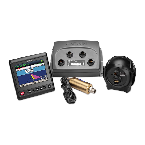
Garmin GHP 10 Instrukcja instalacji - Strona 6
Przeglądaj online lub pobierz pdf Instrukcja instalacji dla Morski system GPS Garmin GHP 10. Garmin GHP 10 48 stron. Autopilot system, addendum
Również dla Garmin GHP 10: Instrukcja instalacji (26 strony), Instrukcja obsługi (28 strony), Deklaracja zgodności (1 strony), Odniesienie (1 strony), Uwagi dotyczące konfiguracji (14 strony)

Ignition or
in-line switch
Red (+)
9–1 Vdc
Black (-)
A fuse
Drain (-)
Pump
(compact .1 L pictured)
notes:
•
This diagram is for planning purposes only. Specific wiring diagrams are included in the detailed installation instructions for
each component. Hydraulic connections are not shown in this diagram.
•
If your boat uses an electrical system that provides more than 12 Vdc, or if you sporadically receive tachometer errors, install an
external tachometer filter (010-11399-00). Contact your local Garmin dealer or Garmin product support for more information.
•
Connect an optional NMEA 0183-compatible GPS device to the data cable on the GHC 10. See
•
Connect an optional NMEA 2000-compatible GPS device to the NMEA 2000 network. See
* Newer ECU units are compatible with 24 Vdc systems. See
* Newer ECU units are compatible with 24 Vdc systems. See
CCU ground
NMEA 000 network (see
NMEA 000 power cable
ECU
POWER
PUMP
CCU
1 Vdc*-0 A fuse.
See
page
for
cable size and length
requirements.
GHP 10 General Wiring outline
Black (-)
page
0)
ENCODER
CCU/ECU Interconnect cable
page 25
page 25
for more information.
for more information.
Yellow CCU signal wire
(see
page
9)
GHC 10
For tachometer wiring,
see
page 7
CCU
Orange - unconnected
Red (+) White (+)
Blue (-) Black (-)
Red (+)
Brown (+)
Black (-)
Black (-)
Yellow CCU signal wire (see
page 32
page 32
for more information.
GHP 10 Marine Autopilot System Installation Instructions
}
Boat tachometer
Alarm buzzer
Shadow Drive
page
9)
for more information.
