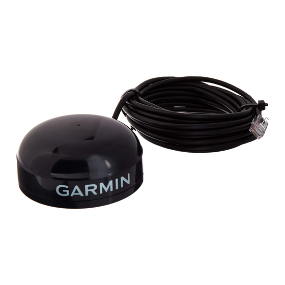
Garmin GPS 17N Instrukcja instalacji - Strona 4
Przeglądaj online lub pobierz pdf Instrukcja instalacji dla Morski system GPS Garmin GPS 17N. Garmin GPS 17N 8 stron. Gps 16/17 series
Również dla Garmin GPS 17N: Informacje techniczne (30 strony), Deklaracja zgodności (1 strony), Specyfikacja techniczna (40 strony)

GPSMAP 2006 / 2010 / GPS 17N Installation Guide
Installing the GPS 17N
The GPS 17N installs on any standard 1" OD Marine Mount. The cable can be
run externally or if possible, through the center of the mount. The GPS 17N con-
nects to the 18-pin Power/Data Cable on the GPSMAP 2006/2010 and provides the
GPS signal for the unit.
The antenna should be mounted in a location that has a clear, unobstructed view
of the sky in all directions to ensure the best reception. Avoid mounting the antenna
where it will be shaded by the boat' s superstructure, a radome antenna, or mast.
Sailboat users should avoid mounting the antenna high on the mast to prevent inac-
curate speed readings caused by excessive heeling. The unit will provide more stable
readings if it is located nearer to water level. Most marine VHF and LORAN antennas
should not seriously degrade the GPS antenna' s reception. It is recommended that
the antenna be mounted at least 3 ft. away from (preferably above) the path
of any radar beam. If interference is experienced, relocate the antennas further
apart. Never paint the GPS antenna or clean it with harsh solvents.
Mounting the GPS 17N with cable outside mount:
1. Place the cable in the vertical slot along the side of the base of the unit.
2. Screw the GPS 17N onto the mount. Make sure that you do not overtighten the
head. It is possible to tighten the unit to the point that the cable may be cut in two.
3. With the GPS 17N and mount installed, fi ll the remaining gap in the cable exit on
the with a marine sealant.
4. When running the cable, attempt to keep the cable away from sources of electronic
interference.
Mounting the GPS 17N with cable through mount:
1. Position the mount in the desired location and mark the approximate center of the
mount
2. Drill a hole large enough for the cable to pass through at the marked location.
3. Slide the cable through the mount and screw the GPS 17N onto the mount.
4. Fasten the mount to the boat
5. When running the cable, attempt to keep the cable away from sources of electronic
interference.
GPS 17N with cable run internally
Three common sources of interference for GPS signals are:
ABOVE- OK
Radar
BELOW- OK
Radar
EMI
EMI (Electromagnetic Interference) from
engine components
GPS 17N
GPS 17N with cable run externally
3'
VHF Radio Antenna
