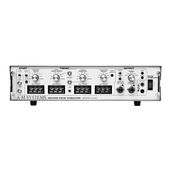
A-M Systems 2100 Instrukcja obsługi - Strona 15
Przeglądaj online lub pobierz pdf Instrukcja obsługi dla Przyrządy pomiarowe A-M Systems 2100. A-M Systems 2100 19 stron. Isolated pulse stimulator

TRIG IN to OUTPUT delay
(DELAY set to 0), output set to
2 V
Timing jitter from TRIG IN to
OUTPUT (for TTL trigger input
with risetime <10 ns)
Timing jitter from TRIG OUT
(either BURST or PULSE) and
OUTPUT
Trigger output to pulse output
delay
Output characteristics
Pulse level error (voltage mode:
open circuit; current mode: short
circuit
Biphasic level difference
| V+ + V- | /2
Baseline level error (voltage mode:
open circuit; current mode: short
circuit)
Risetime (2.5 V out)
Risetime (25 V out)
Transient response
Output impedance (voltage mode)
Output impedance (current mode)
Isolation resistance
A-M Systems
C
C
C
C
A
C
A
A
A
A
C
C
A
131 Business Park Loop, P.O. Box 850 Carlsborg, WA 98324
Telephone: 800-426-1306 * 360-683-8300 * FAX: 360-683-3525
E-mail: [email protected] * Website:
(monophasic)
approx. 0.5 µs for a load of no
more than 10 KV in parallel with
50 pF
< 125 ns (all rates except 100s)
< 1.25 µs (100s rate)
Less than 20 ns (all rates)
approx. 350 ns
< 0.3% of setting + 0.5% of r
range (plus an additional 0.5 µA
in 100 µA range)
< 0.3% of range (voltage
modes: into open circuit;
current modes: into short circuit)
< 0.3% of setting of setting +
0.1% of range (plus an
additional 0.5 µA in 100µA
range)
≈ 200 ns into less than 30 pF
≈ 1.5 µs into less than 30 pF
< 8% overshoot into less than
30 pF for pulse voltages
different than baseline voltage
by at least 10% of range
≈ 50 ohms
>>10 GΩ (typically 200 GΩ)
>>100 MΩ
http://www.a-msystems.com
12
