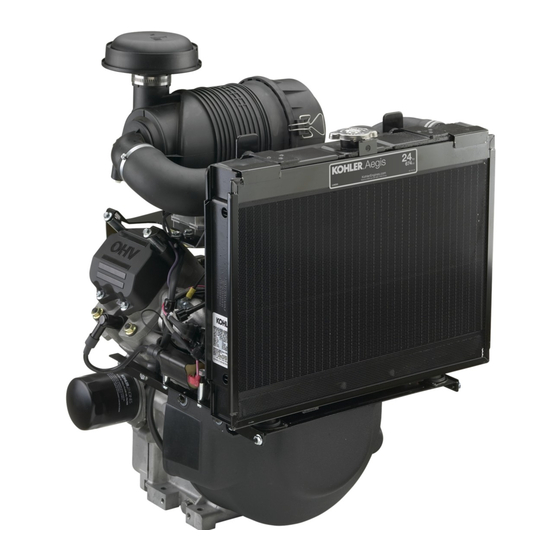
Kohler Aegis LH640 Instrukcja obsługi - Strona 13
Przeglądaj online lub pobierz pdf Instrukcja obsługi dla Silnik Kohler Aegis LH640. Kohler Aegis LH640 21 stron. Horizontal-shaft
Również dla Kohler Aegis LH640: Instrukcja obsługi (8 strony)

3. After the main element is removed, check the
condition of the inner element. It should be
replaced whenever it appears dirty, typically
every other time the main element is replaced.
Clean the area around the base of the inner
element before removing it, so dirt does not get
into the engine. See Figure 17.
Figure 17. Removing Inner Element.
4. Do not wash the paper element and inner
element or use pressurized air, this will damaged
the elements. Replace dirty, bent, or damaged
elements with new genuine Kohler elements as
required. Handle new elements carefully; do not
use if the sealing surfaces are bent or damaged.
5. Check all parts for wear, cracks, or damage.
Replace any damaged components.
6. Install the new inner element, Kohler Part No.
25 083 04-S followed by the outer element, Kohler
Part No. 25 083 01-S. Slide each fully into place in
the air cleaner housing.
7. Reinstall the end cap so the dust ejector valve is
down and secure with the two retaining clips.
See Figure 18.
Figure 18. Air Cleaner Assembly.
Air Intake System and Air Cleaner
Components
Air Cleaner Housing/End Cap Assembly
Make sure air cleaner housing including the dust
ejector valve and the end cap is in good condition and
not cracked. The two retainer clips should positively
lock when cap is installed.
Air Cleaner Hose
Inspect the air cleaner hose to make sure it is not
cracked, split or damaged. Check that the air cleaner
hose is securely clamped to both the air cleaner outlet
and the inlet elbow on the carburetor.
Air Cleaner Mounting Base
Make sure the base is securely fastened to the upper
valve cover screw locations and the screws securing
the clamp bracket for the air cleaner housing are
properly installed and tight.
Breather Tube
Make sure the tube is in good condition and is
properly secured to both the breather cover and
elbow adapter.
Cooling Fan Assembly, Belt, and Drive Pulleys
The cooling fan assembly, used to draw the air in and
across the radiator, is attached to a hub and pulley
assembly with sealed ball bearings. It is belt driven
by a lower split pulley attached to the flywheel and
requires very little service or maintenance. DO NOT
operate the engine without the fan and cooling
system functioning properly, or engine damage will
occur. See Figure 19.
Belt
Dust Ejector
Valve
Lower
Split Pulley
Assembly
Figure 19. Cooling System Belt Drive (Cover and
Radiator Removed For Clarity).
1. Inspect the fan for any cracks, damaged/missing
fan blades, and secure mounting.
2. The bearings, within the bearing carrier in the
hub of the pulley, should rotate smoothly,
without roughness, binding, or play/wobble.
Cooling
Fan
Pulley
Assembly
Radiator
Support
13
