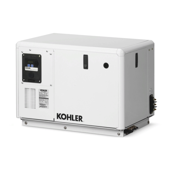
Kohler 6EKOD Instrukcja instalacji
Przeglądaj online lub pobierz pdf Instrukcja instalacji dla Przenośny generator Kohler 6EKOD. Kohler 6EKOD 16 stron. Marine with adciid controller
Również dla Kohler 6EKOD: Instrukcje instalacji (4 strony), Instrukcja instalacji (13 strony)

Original Issue Date: 2/17
Model: 5- -10EKD/4- -8EFKD, 6EKOD/5EFKOD, 9- -11EKOZD/7- -9EFKOZD
Market: Marine
Subject: Two-Inch (NMEA 2000) Digital Gauge Kit GM96999-KP1
Introduction
The remote two-inch digital gauge has controls that
allow starting, stopping, resetting select faults, and
monitoring of generator set functions The two-inch
remote digital gauge can be used with the marine
generator models/controllers shown in Figure 1. See
Figure 2 for the remote digital gauge.
Model
Controller
5--10EKD
4--8EFKD
6EKOD
5EFKOD
9--11EKOZD
7--9EFKOZD
Figure 1 Kit Number for Model with Controller Type
4
1. START (up) arrow button
2. MODE button
3. STOP (down) arrow button
4. LCD display
Figure 2 Gauge Pushbuttons
The gauge communicates with the generator set
model(s) listed above. A 12-pin customer-interface
connector allows connection from the gauge to the
generator set.
Note: Read the entire installation procedure including
safety precautions before beginning installation.
Perform the steps in the order shown.
INSTALLATION INSTRUCTIONS
Kit Number
ADC II
GM96999-KP1
ADC IId
The current software versions are located in TechTools
on the Kohler Power Resource Center. Access the
TechTools site to update the controller software to the
version indicated in Figure 3.
Model
5--10EKD
4--8EFKD
6EKOD
5EFKOD
9--11EKOZD
7--9EFKOZD
Figure 3 Controller Software Updates
Safety Precautions
Observe the following safety precautions while installing
and operating the gauge.
1
2
3
Accidental starting.
Can cause severe injury or death.
Disconnect the battery cables before
working
Remove the negative (--) lead first
when disconnecting the battery.
Reconnect the negative (--) lead last
when reconnecting the battery.
Disabling the generator set.
cause severe injury or death.
generator set or equipment connected to the set, disable the
generator set as follows: (1) Move the generator set master
switch to the OFF position. (2) Disconnect the power to the
battery charger. (3) Remove the battery cables, negative (--)
lead first.
Reconnect the negative (--) lead last when
reconnecting the battery. Follow these precautions to prevent
starting of the generator set by an automatic transfer switch,
remote start/stop switch, or engine start command from a
remote computer.
TT-1715
Controller
Software Version
ADC II
1.8.4
ADC IId
4.4.0
WARNING
on
the
generator
set.
Accidental starting can
Before working on the
2/17
