DeZurik APCO CVS-6000 Instrukcja instalacji, obsługi i konserwacji - Strona 4
Przeglądaj online lub pobierz pdf Instrukcja instalacji, obsługi i konserwacji dla Jednostka sterująca DeZurik APCO CVS-6000. DeZurik APCO CVS-6000 11 stron. Swing check valves
Również dla DeZurik APCO CVS-6000: Instrukcja instalacji, obsługi i konserwacji (19 strony)

DeZURIK
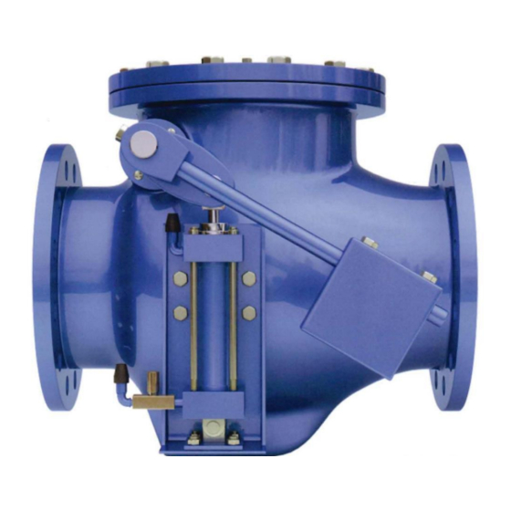
APCO CVS-6000 Convertible Swing Check Valves
Description
A swing check valve consists of a valve body, a bonnet, and a disk that is connected to a hinge. The
disk swings away from the valve-seat to allow flow in the forward direction, and returns to valve-seat
when upstream flow is stopped, to prevent backflow.
Handling and Storage
Lifting the valve improperly may damage it. Do not fasten lifting devices to attached components or
through the seat opening in the body. Lift the valve with slings, chains or cables fastened around the
valve body, or fastened to bolts or rods through bolt holes in the flanges.
If installation will be delayed, place valve indoors in secure, weather tight storage. If temporary outside
storage is unavoidable, make sure a vermin proof rain cover (water shedding tarp, etc.) is secured
around/over the valve to keep off rain and mud. Skid and set the assembly on a flat, solid, and well
drained surface for protection from ground moisture, runoff and pooled rain water.
Installation
•
APCO CVS-6000 Convertible Swing Check Valve may be installed in a horizontal or vertical
position (with the flow upward). In either case, if the CVS-6000-CLW valve is ordered, the
Counterweight Arm (44) should be set 25°-30° below the horizontal line. Unless otherwise
specified, the CVS-6000-CLW valves are shipped for horizontal installation.
•
Before installation, remove foreign material such as weld spatter, oil, grease, and dirt from the
pipeline.
•
Prepare pipe ends and install valves in accordance with the pipe manufacture's instructions for
the joint used.
Do not deflect the pipe-valve joint. Minimize bending stresses in the valve end
connection with pipe loading.
If excessive seat leakage occurs during start-up, recheck the installation and
eliminate any distortion to the valve body.
•
Ensure the valve and pipeline flanges are concentric to ensure proper flange sealing and seat
leakage control.
•
Tighten the flange bolts or studs in a crisscross pattern and minimum of four stages.
• Fusion/Powder Coated Valves
Valves with fusion/powder coated exterior paint require flat washers to be
installed under the flange nuts when installing the valve to the pipeline
flange to prevent the paint from cracking or chipping.
D12009
Page 4
December 2012
