DeZurik AFR3 Instrukcja obsługi - Strona 4
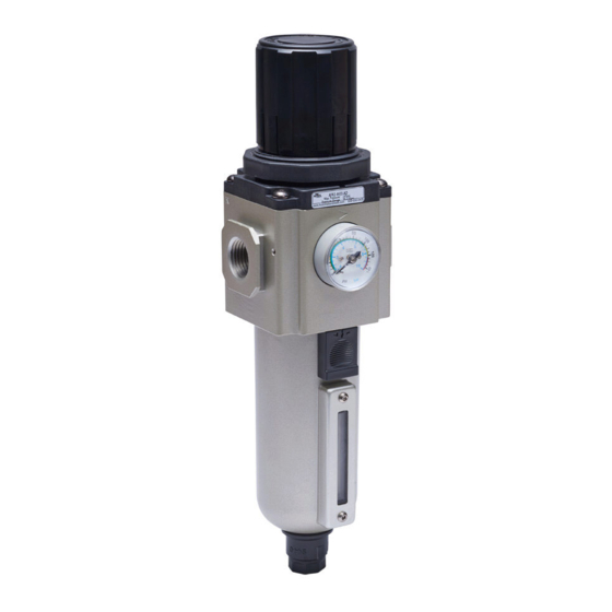
Przeglądaj online lub pobierz pdf Instrukcja obsługi dla Kontroler DeZurik AFR3. DeZurik AFR3 6 stron. Filter regulator used on pneumatic cylinder actuators
Również dla DeZurik AFR3: Instrukcja obsługi (6 strony)

DeZURIK
AFR3 Filter Regulator used on Pneumatic Cylinder Actuators
Maintenance
WARNING!
Failure or improper selection or improper use of the products and/or systems
described herein or related items can cause death, personal injury and property
damage. Depressurize both upstream and downstream pressure.
1. Filter element replacement:
a. Depressurize both upstream and downstream pressure.
b. Remove bowl / bowl guard assembly by pushing up on bowl assembly and turning counterclock-
wise (viewed from below). Clean inside of bowl using a clean, dry cloth. Inspect plastic bowl
for damage and replace if necessary.
c. Remove filter element by turning retainer counterclockwise.
d. Remove old element and discard. Care must be taken at this step not to lose or misplace the valve
spring and valve assembly, as these components may be removed during this procedure.
e. Install a new filter element and reassemble in reverse order. See table side for torque val-
ues.
2. Valve assembly:
a. Depressurize both upstream and downstream pressure.
b. Remove bowl / bowl guard assembly and element retainer assembly as outlined in mainte-
nance Step #1. Care must be taken at this step not to lose or misplace the valve spring and
valve assembly, as these components may be removed during this procedure.
c. Remove the valve spring and valve assembly, if not already done.
d. Inspect all seals and components for damage and replace as required. Clean seals and
components with mild detergent and water (No Solvents!). Use a clean, dry cloth to wipe
any contamination from the valve seat inside the body.
e. Lubricate valve stem and lower valve O-ring seal with a light coat of lubricant.
f.
Reassemble in reverse order. See table on reverse side for torque values.
3. Main Spring and Diaphragm:
a. Depressurize unit, both upstream and downstream.
b. Turn adjusting knob counterclockwise to remove all spring force, then remove bonnet by
turning counterclockwise.
c. Remove adjusting screw assembly, main spring, slip ring and diaphragm assembly.
d. Inspect diaphragm and the relief seat, on relieving models, for damage or contamination.
Replace diaphragm assembly if necessary. Clean relief seat with a soft, dry cloth. Reassemble
in the reverse order making sure slip ring is properly positioned on top of the diaphragm. Bon-
net torque values are shown in the table below.
August 2013
Page 4
D11033
