DeZURIK
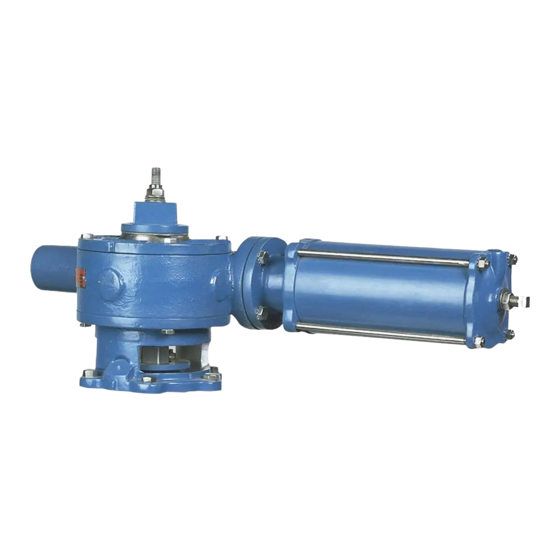
Cylinder Operated G-Series Actuator
Changing Mounting Positions
The actuator can be mounted in 90° increments around the valve stem.
1.
Discontinue flow and relieve pipeline pressure.
Accidental operation of power actuator can cause personal injury or equipment damage.
Disconnect and lock out power to actuator before servicing.
2. Place the valve in the closed position.
3. Relieve actuator supply pressure, and then disconnect the air supply tubing from the valve
assembly.
4. Scribe a line on the valve and actuator. This line will be used for alignment when the actuator
is reassembled on the valve.
5. Note the position of the pointer, then remove the pointer screws and pointer.
6. Remove the cover bolts and cover from the actuator.
Note: It may be necessary to drive a chisel between the cover and actuator housing to loosen
the cover.
7. Mark the rack and gear teeth to indicate which teeth are engaged so the gear can be
reinstalled in the correct orientation.
8. Lift the gear sector out of the actuator; be careful not to lose the actuator drive key.
9. Remove the screws fastening the adaptor to the valve, then lift the actuator and adaptor off
the valve.
10. Remove the gear sector seal from the top cover.
11. Scrape the old gasket material from the top cover and actuator housing.
12. Grease the new seal and press it into the top cover.
13. Line up the scribe marks made earlier, than fasten the adaptor to the valve with the six bolts.
14. Place the actuator drive key in the keyseat in the valve shaft.
15. Pack the gear sector teeth with grease and slide the gear sector down the valve shaft, making
sure it is in the position noted before removal.
16. Place a new gasket on the actuator housing, then fasten the cover in place.
17. Fasten the pointer to the top of the gear sector.
18. Connect the air supply tubing to the cylinder.
19. Check the stop settings and readjust if necessary. The correct adjustment procedure is
described in the STOP ADJUSTMENT section of this Instruction.
20. Pipeline flow and pressure may now be restored.
D10082
Page 10
October 2012

