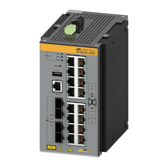
Allied Telesis IE340L-18GP Instrukcja szybkiej instalacji
Przeglądaj online lub pobierz pdf Instrukcja szybkiej instalacji dla Przełącznik Allied Telesis IE340L-18GP. Allied Telesis IE340L-18GP 4 stron. Industrial ethernet layer 3 switches

Quick Installation Guide
IE340 Series
Industrial Ethernet Layer 3 Switches
Installation Guide
This document contains a short version of the installation instructions for the
IE340-12GP, IE340-12GT, IE340-20GP, and IE340L-18GP Industrial Ethernet Layer 3
switches. For complete installation instructions and safety statements, refer to the
IE340 Series Installation Guide on the Allied Telesis web site at
alliedtelesis.com/us/en/library/search.
Safety and Electromagnetic Emissions Certificates
For Safety and Electromagnetic Emissions certificates, see the IE340 Series Installation
Guide.
Informationen zu Sicherheitszertifikaten und Zertifikaten für elektromagnetische
Emissionen finden Sie im IE340 Series Installation Guide.
Para obtener los certificados de seguridad y emisiones electromagnéticas, consulte la
IE340 Series Installation Guide.
Pour les certificats relatifs à la sécurité et aux émissions électromagnétiques, consultez le
IE340 Series Installation Guide.
Per i certificati di sicurezza ed emissioni elettromagnetiche, consultare la IE340 Series
Installation Guide.
För säkerhets- och elektromagnetiska emissionscertifikat, se IE340 Series Installation
Guide.
U.S. Federal Communications Commission
This device complies with Part 15 of FCC Rules. Operation is subject to the following two
conditions: (1) this device must not cause harmful interference, and (2) this device must
accept any interference received, including interference that may cause undesired
operation.
VCCI Statements
この装置は、クラスA情報処理装置です。この装置を家庭環境で使用すると電波妨害を
引き起こすことがあります。この場合には使用者が適切な対策を講ずるよう要求される
ことがあります。VCCI-A
Industrial Canada
This Class A digital apparatus complies with Canadian ICES-003.
Cet appareil numérique de la classe A est conforme à la norme NMB-003 du Canada.
Grounding and Bonding Requirements
Electrical systems and communication cabling systems that are required to be grounded
must be connected to earth. Grounding and bonding provide reliable means to safely
conduct voltages generated by lightning, line surges, or unintentional contact with high
voltages lines or equipment to ground.
The users of the plant or those responsible for the installation shall institute the
necessary measures (e.g., shielding, bonding, and grounding protection) to assure all
components are on the ground fault path. Inappropriate grounding and bonding shall
render all warranties null and void.
Refer to the IE340 Series Installation Guide for recommended practices.
*613-003145 Rev A*
613-003145 Rev. A
Physical Descriptions
For physical descriptions of the switches, refer to the IE340 Series Installation Guide.
Package Contents
Here are the pre-installed components on the switch:
Dust covers on the
Dust cover on
Dust covers on the
twisted pair and
the USB port
Console ports
(See Note)
One M4x8 Phillips
One 4-pin connector on
-head grounding
the DC power PWR 1
and PWR 2 connectors
Note: The IE340L-18GP Switch does not have a USB port.
Here are the items in the accessory kit.
Two wall brackets
Five M4x8 Phillips-head
screws (one spare)
Here are the tools and materials you need for the installation:
Ground wire
–
One solid ground wire (recommended #16 AWG
solid wire)
–
One heat-shrink tube
–
Ring-terminal lug
Power wires
–
Two or four stranded power wires (recommended
18 AWG stranded wire. Do not use wire heavier
than 16 AWG).
–
One or two 2-wire connectors to connect the power
wires to the AC/DC rectifiers or UPS units.
Alarm
–
External sensor for the Alarm In (ALM IN)
connectors
connector and/or external alert device for the Alarm
Out (ALM OUT) connector
–
24 to 18 AWG stranded wire properly rated for the
installation site, maximum length of two meters
DIN rail
–
35 x 7.5mm DIN rail
installation
–
Two DIN rail end clamps (optional)
1
Installation Options
Two 2-pin connectors on
SFP+ ports
the Alarm IN (ALM IN)
This quick installation guide explains how to install the switch on a DIN rail or concrete
and Alarm Out (ALM
wall.
OUT) connectors
For instructions on installing the switch on a wooden wall or in an outdoor enclosure,
refer to the IE340 Series Installation Guide.
screw
One DIN rail bracket on
Installing the Switch on DIN Rail
back panel
To install the switch on a DIN rail, perform the following procedure:
1. Hold the switch vertically with both hands, with the back panel next to the DIN rail.
2. Hook the bottom flange on the DIN rail into the bottom slot on the DIN rail bracket on
One serial Console
management cable
3. Press upwards on the bottom panel of the switch to compress the springs on the DIN
2
Concrete wall
–
Four wall anchors and screws
installation
Tools
–
#1 flat-head screwdriver
–
Phillips-head screwdriver
–
Wire insulator stripper
–
Wire crimper tool
–
Heating device for the heat-shrink tube
–
Drill with 1/4" carbide drill bit (concrete wall
installation)
Note
The switch's maximum operating temperature depends on its orientation on the wall
and the type of enclosure. Allied Telesis recommends installing the device vertically
for best possible airflow and cooling. See the following figures.
Note
For outdoor environments, the switch must be installed in a UL-listed Type 3X or 4X
enclosure to meet safety requirements.
the switch.
Bottom slot on DIN
rail bracket
rail bracket, and pivot the switch until vertical.
Bottom flange on DIN
rail
3
