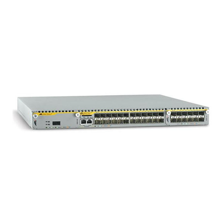
Allied Telesis x900 Series Instrukcja instalacji - Strona 10
Przeglądaj online lub pobierz pdf Instrukcja instalacji dla Przełącznik Allied Telesis x900 Series. Allied Telesis x900 Series 13 stron. Removable power supply and fan
Również dla Allied Telesis x900 Series: Jak skonfigurować (9 strony)

Removable Power Supply and Fan
Table 2: LEDs on the switch reporting PSU status
LED
PSU 1
PSU 2
10
State
Description
Green
PSU 1 is installed and supplying power to the switch. The
voltage output is within specification.
Red
One of the following:
•
PSU 1 is installed in the switch and has exceeded its
recommended temperature threshold of 75º C
(167º F), or the fan has failed.
•
A FOM is installed in the switch and has failed.
•
The bay is empty. Applies to AT-8948, AT-9924T/4SP,
and AT-9924Ts switches since they require a FOM
when only one PSU is installed.
•
PSU 1 is not receiving power when dual PSUs have
been installed.
Off
A FOM is installed and operating at an acceptable speed.
For AT-9924T and x900-48FE switches, a blanking panel
is installed.
Green
PSU 2 is installed and supplying power to the switch. The
voltage output is within specification.
Red
One of the following:
•
PSU 2 is installed in the switch and has exceeded its
recommended temperature threshold of 75º C
(167º F), or the fan has failed.
•
A FOM is installed in the switch and has failed.
•
The bay is empty. Applies to AT-8948, AT-9924T/4SP,
and AT-9924Ts switches since they require a FOM
when only one PSU is installed.
•
PSU 2 is not receiving power when dual PSUs have
been installed.
Off
A FOM is installed and operating at an acceptable speed.
For x900-48FE switches, a blanking panel is installed.
