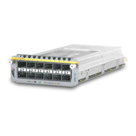
Allied Telesis XEM-12S Instrukcja instalacji - Strona 9
Przeglądaj online lub pobierz pdf Instrukcja instalacji dla Sprzęt sieciowy Allied Telesis XEM-12S. Allied Telesis XEM-12S 11 stron. Expansion module
Również dla Allied Telesis XEM-12S: Instrukcja instalacji (17 strony)

RJ-45 Ports
The 12-port RJ-45 expansion module, model XEM-12T, features the following:
■
two rows of 6 RJ-45 ports
■
gigabit ports that support speeds of 10/100/1000Mbps
■
status LEDs
■
two 16MByte DDR-SDRAM for packet buffering
■
NEBS model XEM-12T-N available
■
cable fault detection and distance-to-fault diagnostics are available for RJ-45
Ethernet ports (see the Test Facility chapter in the Software Reference for the
switch)
Front view XEM-12T
1
2
3
L/A
L/A
D/C
D/C
L/A
L/A
The following LEDs report operations on XEM-12T expansion modules.
LED
State
L/A
Green
(Link Activity)
Green flashing
Amber
Amber flashing 10/100Mbps activity is occurring.
D/C
Green
(Duplex/
Amber
Collision)
Amber flashing Collisions are occurring.
4
5
6
7
8
LINK 1000M
ACT
LINK 10/100M
ACT
Description
A 1000Mbps link has been established.
1000Mbps activity is occurring.
A 10/100Mbps link has been established.
The port is operating in full duplex mode.
The port is operating in half duplex mode.
Installation Guide
9
10
11
12
D/C
FULL DUP
HALF DUP
COL
9
