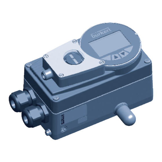
Bürkert 8792 Instrukcja montażu - Strona 2
Przeglądaj online lub pobierz pdf Instrukcja montażu dla Pozycjonery zaworów Bürkert 8792. Bürkert 8792 16 stron. Position controller and process controller with ii 3g ex ec ic iic t4 gc / ii 3d ex tc iiic t135c dc approval
Również dla Bürkert 8792: Instrukcja montażu (16 strony), Dodatkowe instrukcje (12 strony)

3
auThorized use
The external position feedback is designed to be
installed in the Bürkert positioners types 8791, 8792
and 8793.
▶ The external position feedback is not intended for use
in potentially explosive areas. If it is mounted on devices
of Type 8791, 8792 or 8793 which, according to their
designation, are likely to be used in potentially explosive
areas, they must not be used in these areas.
▶ For use observe the conditions described in the chapter
entitled "Technical Data".
▶ The device may be used only in conjunction with third-
party devices and components recommended and
authorized by Bürkert.
▶ Correct transportation, storage and installation; and
careful use and maintenance; are essential for reliable
and faultless operation.
▶ Use the external position feedback only as intended.
english
4
5
General informaTion
5.1 contact addresses
Germany
Bürkert Fluid Control Systems
Sales Center
Christian-Bürkert-Str. 13-17
D-74653 Ingelfingen
Tel. + 49 (0) 7940 - 10 91 111
Fax + 49 (0) 7940 - 10 91 448
E-mail: [email protected]
international
Contact addresses can be found on the final pages of the
printed operating instructions.
And also on the Internet at:
www.burkert.com
5.2 Warranty
The warranty is only valid if the external position feedback
is used as authorized in accordance with the specified
application conditions.
5.3 information on the internet
The operating instructions and data sheets for the Type
8791, 8792 and 8793 can be found on the Internet at:
www.burkert.com
english
6
4
basic safeTy
insTrucTions
These safety instructions do not make allowance for any
• contingencies and events which may arise during the
installation, operation and maintenance of the devices.
• local safety regulations – the operator is responsible for
observing these regulations, also with reference to the
installation personnel.
General Hazardous Situations.
To prevent injury, ensure that:
▶ Installation and start-up may be implemented by autho-
rized technicians only.
▶ After an interruption in the power supply or pneumatic
supply, ensure that the process is restarted in a defined
or controlled manner.
▶ The device may be operated only when in perfect con-
dition and in consideration of the operating instructions.
▶ The general rules of technology apply to application
planning and operation.
6
Technical daTa
Repeating accuracy
Temperature drift
Hysteresis
Operating voltage
Residual ripple
DC rated current
No-load current
l
0
Residual current
Rated insulation voltage
Short-circuit protection
Max. voltage drop at the switching
output compared to operating
voltage
Wire breakage safety /
reverse pole protection
Output function
Switching frequency
Protection class
Type 8791, 8792, 8793
english
5
≤ 2 %
± 10 %
3 ... 15 %
10 ... 30 V DC
≤ 10 % U
ss
≤ 100 mA
≤ 15 mA
≤ 0.1 mA
≤ 0.5 kV
yes / clocking
≤ 1.8 V
yes / complete
Three-wire,
normally open
contact, PNP
≤ 0.02 kHz
IP65, IP67
english
7
