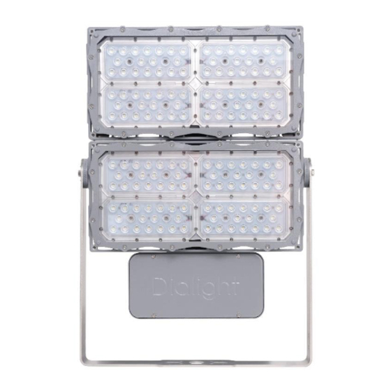
Dialight ProSite Instrukcja instalacji i obsługi - Strona 4
Przeglądaj online lub pobierz pdf Instrukcja instalacji i obsługi dla Światło powodziowe Dialight ProSite. Dialight ProSite 18 stron. For cid2/ciid1/ciid2/ciii
Również dla Dialight ProSite: Instrukcja instalacji i obsługi (9 strony), Instrukcja instalacji i obsługi (20 strony), Instrukcja instalacji i obsługi (8 strony)

Wireless Assembly
Part Number
Description
FLWIRELESS
Wireless Controls
1. Follow Steps 1-4 of the Power Supply
instructions.
2. Disconnect the wireless, 4 position plug
connection (Red, White, Green, & Black)
between the wireless assembly and the
power supply.
3. Remove, 2x M4 screws that hold the
wireless bracket to the driver lid.
4. Collect the replacement wireless assembly
with bracket and install onto the driver lid
with 2x M4 screws. Extra screws provided.
Torque to 20-24 in-lbs. [2.3-2.7 N-m].
5. Follow Steps 7-10 of the Power Supply
instructions.
WARNING: When closing the lid, make sure
wires do not get pinched and that the
wireless card does not get damaged.
Surge Assembly
Part Number
Description
FL10KV277
100-277VAC 10kV Surge
FL10KV480
347-480VAC 10kV Surge
1. When opening the front access lid on the
luminaire, loosen the 4x 10-32 captive
screws.
NOTE: The lid is retained to the luminaire via a
braided wire.
2. If present, remove the currently installed
surge assembly. Disconnect the input and
output plugs. Remove the ground wire
from the earth/ground position of the
terminal block.
3. Removing the 2x M4 screws.
9100FLM00905 REV A
Page 4 of 18
ProSite Floodlight Replacement Parts & Accessories
4. Install the replacement Surge Assembly
with the 2x M4 screws.
Torque to 20-24 in-lbs. [2.3-2.7 N-m].
NOTE: 2x M4 screws come with this assembly.
For
upgrades,
these are
replacements, these are extra screws.
5. Connect the input and output plugs. Install
the ground wire into the ground/earth
position of the terminal block.
NOTE: For instances when the Surge assembly
is an upgrade, the input harness of the Surge
Assembly should be connected to the
harness coming from the input terminal block.
The output harness of the Surge Assembly
should be connected to the harness that was
previously plugged into the harness coming
from the terminal block.
6. Close the front access lid onto the
luminaire using the 10-32 captive screws.
Torque to 30-33 in-lbs. [3.4-3.7 N-m].
WARNING: When closing the lid, make sure
wires do not get pinched.
7. Power the luminaire on and insure proper
function.
Lens Frame Assembly
Part Number
FLGLASSLG
Glass Lens, Grey
FLGLASSWLZ
Glass Lens, Bronze
FLPCLG
PC Lens, Grey
FLPCLZ
PC Lens, Bronze
1. If present, remove window frame assembly
from luminaire, by loosening the 12x 10-32
captive screws and removing the lens
frame assembly.
2. Install the replace window assembly with
the attached captive screws, 12x 10-32.
Torque to 30-33 in-lbs. [3.4-3.7 N-m].
Wire Guard
required.
For
Part Number
FLWG
NOTE: FLWG is shipped with 1x wire guard. F2
models will require 2x FLWG per unit.
1. Install the wire guard using the 4x pre-
installed 10-32 captive screws into the light
engine heatsink. F2 models will require this
to be done on each light engine heatsink.
Torque to 30-33 in-lbs. [3.4-3.7 N-m].
Description
Dialight, 1501 Route 34 South, Farmingdale, NJ, USA 07727
Tel: +1 732 919 3119 Fax: +1 732 751 5778
Description
Wire Guard
Wire Guard & Visor
Screw Locations
www.dialight.com
