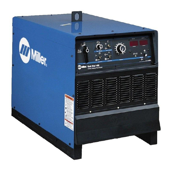
Miller 907364 Instrukcja obsługi - Strona 40
Przeglądaj online lub pobierz pdf Instrukcja obsługi dla System spawania Miller 907364. Miller 907364 48 stron. Ce and non-ce arc welding power source

Item
Diagram
No.
marking
. . . . . . . . .
TP1,2
. . .
175 405
. . . . . . . . .
TP4,5
. . .
168 891
. . . . . . . . .
PLG13
. .
218 413
. . . . . . . . .
RC13
. . .
218 408
. . .
27
. . . . . . . . . . . . .
161 294
. . .
28
. . . . . . . . . . . . . .
Fig 8-2
. . .
29
. . . .
SR1
. . . .
175 070
. . .
29
. . . .
SR1
. . . .
192 672
. . .
29
. . . .
SR1
. . . .
192 671
+When ordering a component originally displaying a precautionary label, the label should also be ordered.
*Recommended Spare Parts.
Part of Option 195 048 Ground Current Sensor
To maintain the factory original performance of your equipment, use only Manufacturer's Suggested
Replacement Parts. Model and serial number required when ordering parts from your local distributor.
OM-222 Page 36
Part
No.
Description
Figure 8-1. Main Assembly (Continued)
. .
THERMOSTAT, NC (Included w/T1)
. .
THERMOSTAT, NC (Included w/T1)
. .
HOUSING, plug pin/skt (service kit)
. .
HOUSING, plug pin/skt (service kit)
. .
BRACKET, mtg rectifier
. .
PANEL, front w/components
. .
RECTIFIER, si diode (Fig 8-3)
. .
RECTIFIER, SCR main (Fig 8-4)
. .
RECTIFIER, SCR main (Fig 8-4)
. . . . . . . . . . . . . . . . . . . . . .
. . . . . . . . . . . . . . . . . . . . . .
. . . . . . . . . . . . . . . . . . . . . .
. . . . . . . . . . . . . . . . . . . . . .
. . . . . . . . . . . . . . . . . . . . . . . . . . . . . . . . .
. . . . . . . . . . . . . . . . . . . . . . . . . . . . .
. . . . . . . . . . . . . . . . . . . . . . . . . . .
. . . . . . . . . . . . . . . . . . . . . . . . . . . . . . .
. . . . . . . . . . . . . . . . . . . . . . . . . . . . . . . . . . . .
Quantity
Model
302 452 652
402 602 852
2
. . .
2
. . .
2
2
. . .
2
. . .
2
1
. . .
1
. . .
1
1
. . .
1
. . .
1
2
. . .
2
. . .
2
1
. . .
1
. . .
1
1
1
1
