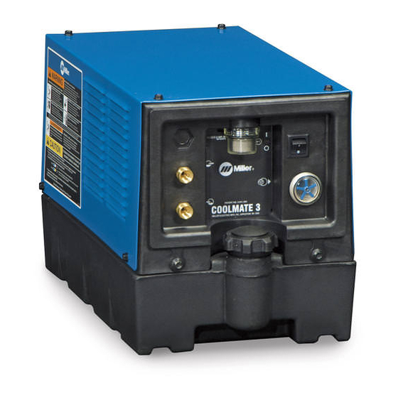
Miller COOLMATE 1 CE Instrukcja obsługi - Strona 12
Przeglądaj online lub pobierz pdf Instrukcja obsługi dla System spawania Miller COOLMATE 1 CE. Miller COOLMATE 1 CE 20 stron.
Również dla Miller COOLMATE 1 CE: Instrukcja obsługi (17 strony)

5-2. GMAW Connections
3
5
6
!
Do not move or operate unit where
it could tip.
!
230 volt AC coolers only: Replace
power cord plug if supplied plug
does not match receptacle. Have a
qualified person install correct 230
volt AC plug according to national
and local codes.
1
Lift -Eye
If placing cooling unit on welding power
source, slots are provided in bottom of unit
so it fits over lift-eye.
To prevent overheating, make sure cooling
unit is positioned so airflow is not restricted.
OM-248 626 Page 8
1
2
4
2
115 Or 230 Volt AC Grounded Re-
ceptacle (Depending On Model)
An individual circuit capable of carrying 15
amperes and protected by fuses or circuit
breakers
is
recommended.
mended fuse or circuit breaker size is 15
amperes. For 230 volt models, an individu-
al branch circuit capable of carrying 10 am-
peres and protected by fuses or circuit
breakers
is
recommended.
mended fuse or circuit breaker size is 10
amperes.
NOTICE − If welding power source has a
water valve, do not connect hoses to water
valve. Connect hoses as shown.
Tools Needed:
3
Coolant Out Hose
4
Coolant In Hose
Fittings have 5/8-18 left-hand threads.
Connect hoses with proper fittings as
Recom-
shown.
5
Coolant Tank Cap
Use table in Section 4-4 to select proper
coolant, and fill tank. Maintain coolant level
Recom-
at approximately 1 in. (25 mm) below top of
filler neck.
6
Power Switch
Operation:
Turn power switch On.
5/8 in.
801 191-D
