Miller XT40 Torch Podręcznik - Strona 21
Przeglądaj online lub pobierz pdf Podręcznik dla System spawania Miller XT40 Torch. Miller XT40 Torch 40 stron.

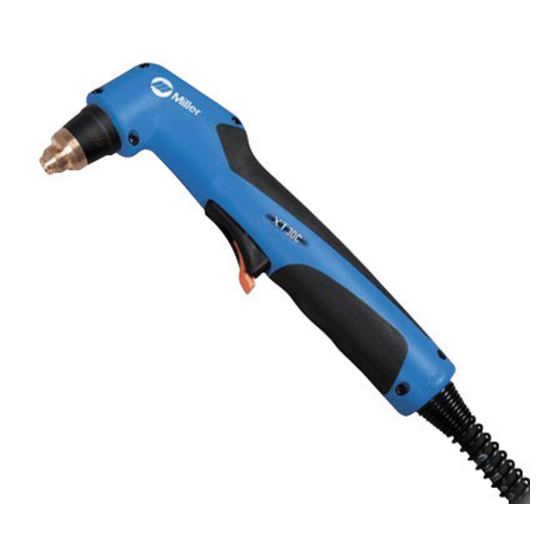
4-4. Installing 30 Ampere (XT30C) Torch And Work Cable On Spectrum 375
(Stock No. 903 891), And Using Trigger Safety Lock
7
6
5
5
6
Trigger Locked
Tools Needed:
1/4 in.
8
2
3
3
4
9
7
4
1
10
Trigger Unlocked
If torch or work cable needs to be
removed or replaced, proceed as
follows:
!
Turn
power
Off,
disconnect input power plug
from receptacle.
Remove wrapper from unit.
Torch Connections
Remove existing torch cable from
unit.
1
Solenoid Fitting
Replace existing solenoid fitting
with supplied fitting (Part No.
255157).
2
Strain Relief
3
Torch Cable
Insert cable through strain relief.
Slide strain relief nut onto torch
cable, but do not tighten.
4
Air Line Connector
Insert air line connector into
solenoid fitting.
5
Plug PLG1/Receptacle RC1
Connect PLG1 from torch to
receptacle RC1 on end of wiring
harness connected to circuit board
PC1.
6
Ring Terminal And Terminal
PILOT
Connect ring terminal on end of red
leads to PILOT terminal.
7
Ring Terminal And Terminal
L2−RED
Connect ring terminal on end of
white leads to L2−RED terminal.
Tighten strain relief nut.
Tighten strain relief around cable.
Work Cable Connections
Remove existing work cable from
unit.
8
Strain Relief
.
Be sure to allow some work
cable slack inside the unit.
Insert work clamp lead through
strain relief, and install strain relief
into front panel.
9
Work Lead Ring Terminal
Connect ring terminal on end of
work clamp lead to terminal labeled
WORK on circuit board PC1. Route
lead along torch lead bundle.
10 Trigger
Ref. 804 489 / Ref. 802 860 / 200 173-A / 802 877
OM-254 449 Page 17
and
