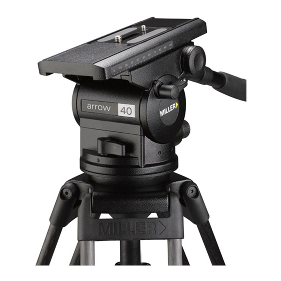
Miller arrow 40 Instrukcja obsługi - Strona 4
Przeglądaj online lub pobierz pdf Instrukcja obsługi dla Akcesoria do kamer Miller arrow 40. Miller arrow 40 13 stron. Fluid head

Technical Data
Weight - kg (lb)
Payload Range - kg (lb)
Max Capacity - kg (lb)
Tilt Drag
Tilt Range
Tilt Lock
Pan Drag
Pan Range
Pan Lock
Counterbalance System
Camera Platform Type
Camera Plate
Mounting Base
Ball Level Range
Handle
Temperature range -
o
C(
o
F)
Construction
Sealing
Finish
Warranty
Arrow 40
3.2 (7.0)
7.0 – 16.0 (15.4 – 35.3)
25 (55.1)
7 Selectable fluid drag positions + 0
+ 90
o
/ -75
o
Positive Lock calliper brake system
7 Selectable fluid drag positions + 0
360
o
Positive Lock calliper brake system
4 Selectable positions (see Fig. 7)
Quick release sliding platform
with 70 mm travel.
1⁄4", 3/8"
Ø100 mm Ball Levelling
15
o
Telescopic black anodised pan handle
with adjustable reach and angle.
-40
o
to +65
o
(-40
o
to +149
o
)
Lightweight diecast Aluminium alloy,
moulded reinforced plastics
Water & Dust resistant
Matt black (low sheen) durable powder
coated with anti-corrosive pre treatment
3 Years
Arrow 55
3.2 (7.0)
10.0 – 25.0 (22.0 – 55.1)
25 (55.1)
7 Selectable fluid drag positions + 0
+ 90
o
Positive Lock calliper brake system
7 Selectable fluid drag positions + 0
360
o
Positive Lock calliper brake system
4 Selectable positions (see Fig. 8)
Quick release sliding platform with
100 mm travel.
1⁄4", 3/8"
Ø100 mm Ball Levelling
15
o
Telescopic black anodised pan handle
with adjustable reach and angle.
-40
o
Lightweight diecast Aluminium alloy,
moulded reinforced plastics
Water & Dust resistant
Matt black (low sheen) durable powder
coated with anti-corrosive pre treatment
3 Years
3
/ -75
o
to +65
o
(-40
o
to +149
o
)
