Panasonic AG-MYA30G - XLR Mic Adaptor Instrukcja obsługi - Strona 6
Przeglądaj online lub pobierz pdf Instrukcja obsługi dla Kamera Panasonic AG-MYA30G - XLR Mic Adaptor. Panasonic AG-MYA30G - XLR Mic Adaptor 48 stron. Xlr microphone adapter
Również dla Panasonic AG-MYA30G - XLR Mic Adaptor: Instrukcja obsługi (10 strony)

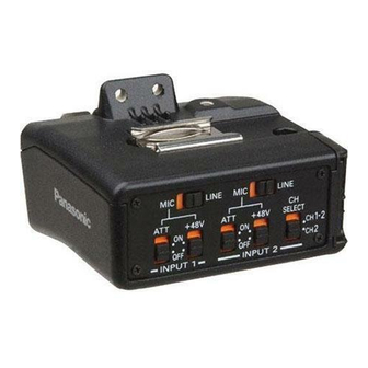
Parts and their functions
3
4
6
5
1Level control
Turn one or both of these controls to
adjust the input level of the sound.
The input levels of the CH1 (left
channel) and CH2 (right channel)
sound can be adjusted separately.
Normally, it is recommended that the
controls be kept at the center position.
Minimum
Maximum
OOnce the unit is mounted on the AG-
DVC30, the audio levels of the mic
input signals can no longer be adjusted
using the controls on the AG-DVC30
(or AG-DVC32).
– 6 (E) –
1
2
2XLR connectors (INPUT1, INPUT2)
Connect a microphone or audio unit
here.
3MIC/LINE switch
Set
the
switch
corresponding to the unit connected to
the
XLR
connector
INPUT2).
LINE:
Set the switch to LINE when an
audio unit has been connected to
the XLR connector.
The input level is 0 dBu.
At this point, set the wind noise
reduction function of the AG-DVC30
(or AG-DVC32) to OFF.
MIC:
Set the switch to MIC when a
microphone has been connected to
the XLR connector.
The input level can be switched
using the ATT switch 4.
4ATT switch
Use this to switch the audio input level.
ON: –50 dBu, OFF: –60 dBu
The switch setting takes effect when
the MIC/LINE switch 3 has been set
to the MIC position.
5+48V switch
When the switch is set to the ON
position, +48V power (power supply for
a phantom microphone) is supplied to
the corresponding XLR connector
(INPUT1 or INPUT2).
When connecting a unit that is not
compatible with the +48V power, set
the switch to the OFF position.
Connecting a non-compatible unit
when the switch is set to the ON
position may cause the unit to
malfunction.
to
the
position
(INPUT1
or
