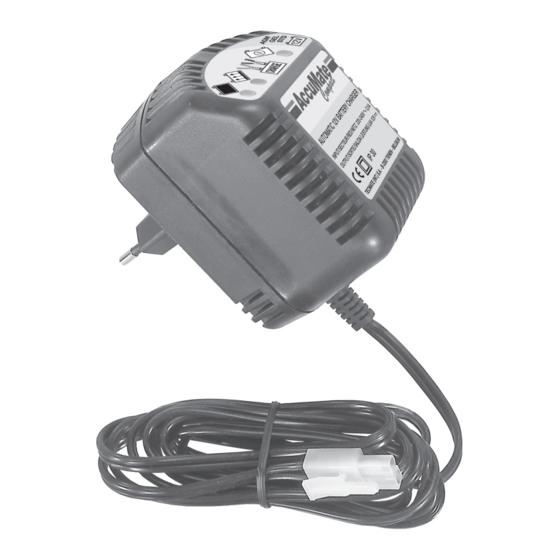
AccuMate TM71 Instrukcja obsługi - Strona 4
Przeglądaj online lub pobierz pdf Instrukcja obsługi dla Zasilanie AccuMate TM71. AccuMate TM71 12 stron.

CHARGING
1) If the device is to be connected to a battery, first ensure that the battery is a 12V battery (which has 6 cells)
and that there is good ventilation around battery and charger.
2) If using the battery clips, connect these to the polarised connector terminating the device's output cable,
then, if the battery to be charged remains connected to a vehicle's electrical system, determine whether the
positive or negative (more commonly) pole of the battery is connected to the vehicle chassis. First connect the
RED clamp to the POSITIVE (POS, P, +) terminal if ungrounded (majority of vehicles) or the BLACK clamp to
the NEGATIVE (NEG, N, -) terminal if ungrounded (unusual), and then the other battery clip to the vehicle
chassis or engine, avoiding any part or location where any fuel or fuel vapour may be present.
3) If using the eyelet connection set, see NOTE in the preliminary text above. Connect the device to the batte-
ry by joining male and female halves of the polarised 2-pin connector.
4) It is important to ensure a good contact between battery clips or eyelets and the battery posts or terminals.
5) Fully insert the device's metal contact pins into a 220-240V AC mains supply socket and if this has a switch,
switch it on. If obstructions close to the wall socket prevent full insertion of the device, the casing of the
device (except the UK model) can be rotated through 90° relative to the contact pins so as to overcome such
difficulties. To achieve this, remove the device from the wall socket. Locate the rotation locking pin close to
the device's AC contact pins. Use a flat tool to lift the locking pin just clear of the locking hole. This allows
rotation through 90° to the alternative locking position. (NOTE : do not lift the locking-pin by more than is
necessary as this can result in its premature failure).
6) Refer to the LED panel explanation above. The power ON LED should light. If not check all connections.
7) Provided that the battery voltage is above 2 Volts, the yellow LED indicating the 2 main charging stages
should light up and continue to indicate steadily during these 2 stages, which comprise a 0,6A constant cur-
rent BULK CHARGE delivered until the sensed battery voltage has risen to 14,3V, followed by the ABSORP-
TION STAGE in which the charge voltage is maintained at 14,3V until such time as the charge current has redu-
ced as the battery approaches full charge, to 300mA.
8) The battery is now close to full charge and the FLOAT MODE green LED will indicate that the charge vol-
tage is now limited at 13,5V. The charger now gently brings the battery to full charge and then maintains
it for as long as connected, allowing the battery to take charge current according to need to sustain its
charge against any small connected loads, losses in the wiring system supported by the battery, or slight
self-discharge of the battery itself.
9) Should these latter factors cause the battery being maintained to need more than 300mA at any time, the
charge programme automatically reverts to the ABSORPTION STAGE so as to offer the battery up to the
maximum 0,6A current if necessary. The yellow CHARGING LED will indicate this reversion. When the battery
has been brought close to full charge again, this will give way to the FLOAT MODE LED.
10) You may observe the FLOAT MODE and CHARGING LEDs indicating alternatively at short intervals for a brief
period following the first indication of the FLOAT MODE LED. This is more probable if the battery has been in
service for a significant length of time or is no longer in the best of condition or is supporting a wiring system
in which there are some electrical losses. If these alternating indications persist and the battery remains
connected to a wiring system, disconnect and remove the battery, then reconnect the charger. The same LED
indications recurring in due course are symptomatic of some internal battery damage. If on the other hand the
FLOAT mode does eventually indicate steadily, this points to electrical losses in the wiring system.
4
