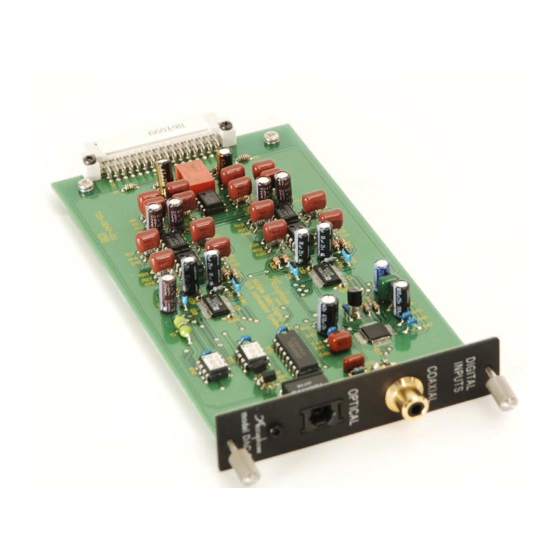
Accuphase DAC-20 Instrukcja obsługi - Strona 2
Przeglądaj online lub pobierz pdf Instrukcja obsługi dla Systemy wejścia/wyjścia Accuphase DAC-20. Accuphase DAC-20 2 stron. Digital input board

Thank you for selecting the Accuphase Digital Input Board DAC-20. This product is a D/A
converter board with coaxial and optical fiber inputs. It is designed for installation in a slot on
the rear panel of an analog Accuphase component, to provide direct input capability for sig-
nals from digital components. Usage details of the board will differ, depending on the Accuphase
component in which the board is installed. To ensure correct operation, please refer to the
instruction manual of the respective Accuphase component before use.
Install the board in the option board slot on the rear panel of an analog Accuphase
component. This allows you to connect the digital output signal from a CD player
or other component.
Connections
"COAXIAL" connector
"OPTICAL" connector
Connection cables
"COAXIAL" connector : 75-ohm coaxial cable
"OPTICAL" connector : Optical fiber cable
Guaranteed specifications
Input format :
Sampling frequency : 32 - 96 kHz, 24 bit
Digital inputs :
Optical fiber cable
If connector has a
connection
blind plug
Remove protective cover
Optical connector
from connector tip
If connector has a
shutter
Plug
Optical fiber
cable
Note
Do connect both the COAXIAL output and any analog output (balanced/unbal-
●
anced) of the source component to the component where the DAC-20 is
installed. If the same component is connected simultaneously via two links in
this way, ground loops may occur which can cause hum and other noise.
When both the COAXIAL and the OPTICAL input are connected, one of the
●
signals will be selected. To control the selection, disconnect the cable for the
component that is currently not playing, or turn power to that component off.
Digital Input Board
Usage
DIGITAL OUT on digital component
JEITA CP-1201/AES-3 compliant
COAXIAL 0.5 Vp-p, 75 ohms
OPTICAL − 27 to − 15 dBm
Pull out blind plug
Align plug guide with
connector and insert
Push inwards to
Plug
open shutter
DAC-20
Note
E-308, C-245, CX-260
For reasons of power supply capacity, it is not possible to use two DAC-20 option
●
boards in the above models. However, the DAC-20 can be used together with an AD-20
(Analog Disc Input Board).
Caution
Do not touch circuit components, solder areas, or exposed parts of connectors,
to prevent possible damage and contact problems. Hold the board only at the
PCB edges or the rear panel.
1
Set the power switch of the Accuphase component to OFF.
2
Loosen the two screws at the top and
bottom and remove the sub panel
covering the option board slot on the
rear panel (see Fig 1).
3
Insert the option board by sliding it
into the top and bottom guide rails
of the slot (see Fig 2). When the board
Plug
touches the internal connector, give
it a slight push until the board is firmly
seated. (The board must be flush with
the rear panel.)
4
Secure the board with the two
screws at the top and bottom.
Caution
Before inserting or removing an option board, be sure to turn the power of the
●
Accuphase component off to prevent the risk of damage.
Tighten the two fastening screws firmly. If the screws are not properly se-
●
cured, ground connection will be impaired and damage may occur.
D071.5X
INSTRUCTION MANUAL
Installation
* The illustration shows the E-550.
Guide rail
7 2
4 -0
7 2
0 1
4 -0
0 2
Sub
panel
Guide rail
Fig. 1
Fig. 2
ACCUPHASE LABORATORY, INC.
2-14-10, SHIN-ISHIKAWA, AOBAKU, YOKOHAMA 225-8508, JAPAN
820-3238-10(K3) Printed in Japan
9 -0
0
0 -0
0
Option
board
