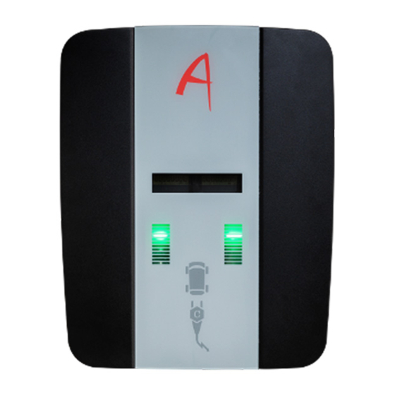
Alphatec AP1eM Specyfikacja techniczna - Strona 11
Przeglądaj online lub pobierz pdf Specyfikacja techniczna dla Ładowarka Alphatec AP1eM. Alphatec AP1eM 19 stron.

Handbuch | Wallbox Power
Erstinspektion /
Initial inspection
•
Öffnen Sie 2 Schrauben von der Unterseite und 2 Schrauben
von der Oberseite, um die Tür zu entfernen
•
Open 2 screws from the bottom side and 2 screws from
the topside to remove the door
1. optische Prüfung / visual inspection
•
Gehäuse, Sockel, Fundament, die Verschraubung der
Komponenten sowie Ladekabel und Ladebuchsen dürfen
keine sichtbaren Schäden aufweisen.
•
Housing, base, foundation, the screw connection of the
components as well as charging cables and charging
sockets should not exhibit any visible signs of damage.
2. funktionstest / functional test
•
Verwenden Sie den Adapter zur Fahrzeugsimulation,
um die einwandfreie Funktion zu überprüfen.
Führen Sie alle relevanten Ladevorgänge durch.
•
Use the adapter for vehicle simulation to check the faultless
function. Run through all relevant charging sequences.
3. Messungen / measurment
•
Prüfung und Messung der Schutzeinrichtungen.
•
Testing and measuring of the protective devices.
4. Schriftlicher Bericht / written report
•
Die Ergebnisse der Inspektion, der Funktionsprüfungen und der
Messungen sind zu dokumentieren und in der Produkt- und Instal-
lationsakte abzulegen.
•
Results of the inspection, functional tests and measurements are to
be documented and filed in the product and installation file.
20
Technische Änderungen unter Vorbehalt | Stand 03/2022 | DB9.0043 | DB9.0044
Handbuch | Wallbox Power
Einstellen des Maximal-Stroms /
Maximum current adjustment
•
Das Einstellen einer Strombegrenzung ist mit dem integrierten
Drehschalter einfach möglich. Dies darf nur von einer Elektro-
fachkraft durchgeführt werden. Der maximale Strom wirkt sich
auf die gesamte Installation, die Stromquelle und das Lade-
verhalten aus. Sie dürfen keine Änderungen an der Einstellung
ohne Ihren Elektriker vor Ort vornehmen.
•
It is possible to set a current limit by using the on board
rotary switch. This should only be performed by a qualified
electrician or ordered with maximum setting. The maximum
current affects the whole installation, power source and
charging behavior. You shall not attempt any changes
to the setting without your local electrician.
3 phase
1 phase
General
1 - 6A
A - 18A
0
2 - 7A
B - 20A
3 - 8A
C - 25A
4 - 9A
D - 32A
5 - 10A
6 - 13A
E - free
7 - 14A
8 - 15A
F - slave
9 - 16A
Technische Änderungen unter Vorbehalt | Stand 03/2022 | DB9.0043 | DB9.0044
21
