ABB ACS800 Multidrive Instrukcja obsługi sprzętu - Strona 6
Przeglądaj online lub pobierz pdf Instrukcja obsługi sprzętu dla Kontroler ABB ACS800 Multidrive. ABB ACS800 Multidrive 20 stron. Asfc switch fuse controller unit for frame r8i inverter modules

6
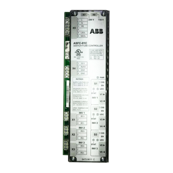
ASFC Connectors
Connecto
r
X1
1
2
3
X2
1
2
3
X3
1
2
3
X4
1
2
3
X5
1
2
3
4
5
6
V1
V2
V3
V4
V5
V6
Hardware description
Signal
Description
Charging circuit connection, Inverter 1. Use ABB specified resistors only.
IR1+
Inverter 1 (+).
NC
Not connected
IR1-
Inverter 1 (-)
Charging circuit connection, Inverter 2. Use ABB specified resistors only.
IR2+
Inverter 2 (+).
NC
Not connected
IR2-
Inverter 2 (-)
Charging circuit connection, Inverter 3. Use ABB specified resistors only.
IR3+
Inverter 3 (+).
NC
Not connected
IR3-
Inverter 3 (-)
Switch fuse status monitoring
+15 V
Excitation voltage for auxiliary contact of switch fuse. Max. 10 mA
AUX2
Digital input from auxiliary contact (on/off status of main contacts)
GND
Ground for control electronics
Power supply input & switch fuse locking solenoid control output
L
230 VAC (or 115 VAC)
N
Neutral
PE
Protective Earth
NC
Not connected
LSOL
230 VAC control pulse for OESL locking solenoid
NSOL
Neutral for OESL locking solenoid
INV1 EN
Optical transmitter (start enable to Inverter 1)
UDC1
Optical receiver (UDC > 80% acknowledgement from Inverter 1)
INV2 EN
Optical transmitter (start enable to Inverter 2)
UDC2
Optical receiver (UDC > 80% acknowledgement from Inverter 2)
INV3 EN
Optical transmitter (start enable to Inverter 3)
UDC3
Optical receiver (UDC > 80% acknowledgement from Inverter 3)
