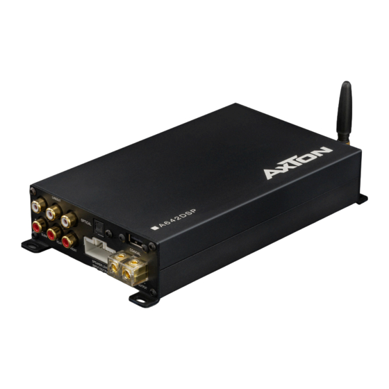
AXTON A642DSP Instrukcja instalacji i obsługi - Strona 3
Przeglądaj online lub pobierz pdf Instrukcja instalacji i obsługi dla Wzmacniacz AXTON A642DSP. AXTON A642DSP 19 stron. 5-ch smart digital amplifier

CONNECTIONS + CONTROLS
INPUTS + OUTPUTS
1
ANTENNA
External Bluetooth antenna of the audio streaming BT module, called "BT Audio"
in your mobile settings. The second BT module, called "A642DSP" is for doing the
adjustments only and does not need a separate antenna.
2
POWER LED
Two color LED: Green light shows normal operation. Green light blinking shows a
current data transfer, i.e. receiving data from the app. Red light shows protection
mode, i.e. too low impedance.
3
POWER TERMINAL
Connect Ground and Battery cables.
4
REMOTE CONTROL
Connect the optional RC for convenient operation of Master Volume, Bass Volume
and Mute function. When you are using the ABT50 with OTG for iPhone for lossless
audio transmission, the signal is sent directly avoiding any converter. That's awesome.
But it also means you are not able to adjust the volume with your iPhone. Therefore
you need to connect the separate available RC.
5
REMOTE / SIGNAL TURN ON
Choose if the amp shall turn on by separate ACC+/Remote wire or by DC Offset signal.
6
FUSE
If the fuse is broken, replace it with a new fuse of same value (30 A).
7
LINE OUT
If you only want to use the DSP function of the A642DSP with a separate high
performance amplifier, connect the line out of the A642DSP with the RCA input of your
amplifier.
8
OPTICAL
Connect to ABT50 for lossless Hi-Res audio transmission from your smartphone.
9
COAXIAL
This input provides power for the ABT50 and also receives audio data from this
device. It's impossible to connect usual USB sticks.
10 SPEAKER LEVEL INPUT/OUTPUT
This is the main connector for optional Plug & Play installation.
11
SUBWOOFER OUTPUT
This is the terminal to connect a subwoofer with minimal impedance of 2 ohms.
4
Side panels
1
5
7
WIRING DIAGRAM
Connector view
20
1*
ACC-in
11
GND
2*
Rem-out
12
+B
3
RR-in
13
FL+out
4
RR+in
14
FL-out
RL-in
FR+out
5
15
6
RL+in
16
FR-out
7
FL-in
17
RL+out
FL+in
RL-out
8
18
FR-in
RR+out
9
19
10
FR+in
20
RR-out
2
3
4
30 A
6
8
9
bm
bl
1* In some cases with old headunits the Auto-Turn-On
function cannot work. If you meet this problem, please
connect the wire "ACC-IN" to ACC/Amp Remote of the
car stereo or another cable which will provide +12 V
only when the car stereo is turned on. Secondly select
"REMOTE TURN ON" on the remote switch.
2* REM-Out: Connect this wire to the remote input of a
separate amplifier.
5
