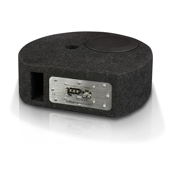
AXTON ATB20STP Instrukcja instalacji i obsługi - Strona 5
Przeglądaj online lub pobierz pdf Instrukcja instalacji i obsługi dla Subwoofer AXTON ATB20STP. AXTON ATB20STP 12 stron. 8"/20 cm active subwoofer

WIRING DIAGRAM
Headunit
REM ON/OFF
i.e. Amp remote
q
FUSE
POWER INPUT
+12V
REM
GND
POWER
PRO
HIGH LEVEL
ON
OFF
AUTO TURN ON
– +
– +
AXB20STP Active Subwoofer
q
Fuse (20A)
+12V Power Terminal
REM (Amp Remote) Terminal
GND Power Terminal
Power/Protect Status LED
Switchable Bass-Boost 0 – 6 dB
Auto Turn-On/Off for High Level Input
High Level Input
RCA Input
DANGER:
Use the specified amperage fuse only.
Higher amperage may cause serious damage or even a fire.
Car battery
12 VDC
MAIN
FUSE
X-OVER SETUP
BASS BOOST
LPF
GAIN
0dB
6dB
50Hz
150Hz
MIN
MAX
R
L
RCA
AUDIO INPUTS
R+L from Low Level Audio Out
of the headunit.
Use a Y Adapter if you want
to directly connect to a mono
subwoofer output.
– 8 –
ADJUSTMENTS
Turn-on your head-unit keeping your volume at the lowest setting. The green status LED on
the front of the ATB20STP amp-module should light up now. If not, turn-off your head-unit
and re-check all wiring to and from the amplifier for missing or faulty connections.
PROTECTION INDICATOR
This active subwoofer is equipped with an overload protection. In case of internal short
Ground
circuit or increased temperature, the overload protection is activated, and the red LED
indicator comes on. Through this the amplifier is protected against damage. In case of the
thermal protection a certain cooling time must be allowed after which the amp-module will
resume operation.
LOWPASS CROSSOVER FREQUENCY ADJUSTMENT
The lowpass cut-off frequency setting, marked as „LPF" on the active subwoofer, depends
on the dimension of the vehicle and the mounting location. As a rule of thumb, settings in
a range between 80 to 100 Hz will render best sonic results. For an intermediate lowpass
crossover setting to attempt input gain and phase-shift control adjustments, go for a VR-pot
set to approx. 80 Hz – and after input gain has been adjusted, it is advisable to fine tune the
lowpass crossover frequency for best possible sound quality.
Note: In general, setting the lowpass crossover frequency too low, will result in a weak
and muddy sounding bass, while setting this crossover frequency too high will result in a
'booming' bass sound and reduced low end extension.
INPUT GAIN
The input level control allows the ATB20STP to be matched to almost any car, to work
well within a wide range of output levels. The following procedure can be applied: Turn on
the head unit and adjust the volume level to an elevated but still sane output. Now using
a screwdriver, increase the GAIN potentiometer by turning it clockwise (on the ATB20STP
side panel) until the bass content is perceived as sufficient and balanced.
BASS BOOST
The bass boost slide switch with positions „0 dB" or "6dB" has to be played by ear. With the
slide switch set to "0 dB", the bass boost is deactivated, with position "6 dB", the frequencies
around 40 Hz are boosted – which will improve the low end extension in smaller compact
type cars. Note that with bass boost enabled, the subwoofer will have less max. dB head-
room since the very low frequencies are amplified with a higher gain and thus, woofer and
amp module reach their respective limits earlier.
– 9 –
