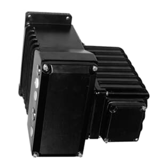
ABB EBN861 Instrukcja - Strona 3
Przeglądaj online lub pobierz pdf Instrukcja dla Kontroler ABB EBN861. ABB EBN861 18 stron. Power electronic units for field installation. for the control of contrac actuators of the pme, lme, rhd or rsd series
Również dla ABB EBN861: Instrukcja obsługi (17 strony)

3. General
3.1
Proper Use
Power electronic units EBN853 and EBN861 may be used exlusively for triggering electrical actuators
of the RSDE... or RHDE ... series. Do not use them for any other purpose. Otherwise, a hazard of per-
sonal injury or of damage to or impairment of the operational reliability of the device may arise.
3.2
Safety and Precautions
When mounting the electronic units in areas which may be accessed by unauthorized persons, take the
required protective measures.
- Only qualified specialists who have been trained for these tasks are authorized to mount and adjust
the electronic units, and to make the electrical connection.
- When working on the electronic units always observe the locally valid accident prevention regula-
tions and the regulations concerning the construction of technical installations.
- Switch-off the voltage supply; make sure that unintentional switching on is not possible
- Make sure that cutting off the voltage supply does not affect the plant process
- Consider restoring process forces from the final control element when cutting off the voltage
4. Storage
The devices may be stored under moist and aggressive condition for a short time. The equipment is
protected against external corrosive influences. However, avoid direct exposure to rain, snow, etc.
Condensation may occur in the terminal box. Therefore, it is protected by a desiccant, which ensures
sufficient protection for approximately 150 days. The desiccant can be regenerated at a temperature of
90° C within 4 h.
Remove the desiccant prior to commissioning the electronic units.
4.1
Actuator operation via frequency converter
- The frequency converter (electronic unit) may not be installed or operated within the hazardous area.
- Check the electronic unit for proper parameter settings.
- Make sure that the electronic unit is connected to tho associated actuator.
- The actuator default settings include the acivation of the positioning loop monitoring. A later de-ac-
tivation is not allowed.
- The hand wheel must be locked with a cotter pin in order to avoid accidental operation. Disconnect
the power supply prior to manual operation.
- Actuators in explosion-proof design do not allow for rapid traverse operation. This function will be
ignored if you select it via the user interafce.
4.2
Long-time Storage
If you intend to store or transport the device for a longer time, we recommend to wrap it in plastic foil
and add desiccant. Regularly check if the desiccant is still active.
5. Delivery settings
Behavior in 0/100% position:
Setpoint function:
Input (setpoint):
Function:
Positioning loop monitoring:
Output (actual value):
1)
Digital inputs:
1)
Digital outputs:
Range:
The configuration of your actuator may differ from the standard configuration specified above. It can be
called up for display using a notebook / PC and the related configuration program.
1)
not with fieldbus communication.
Keep closed with rated torque
Linear; setpoint = positioning value
1)
4 ... 20 mA
Positioner, parameter: setpoint
activated
1)
4 ... 20 mA
DI 1 switch-over manual/automatic and v.v.
DI 2 / DI 3 manual control +/-
DO 1 ready to operate, DO 2/3 end position signalling
Not adjusted (to be adjusted during commissioning)
3
