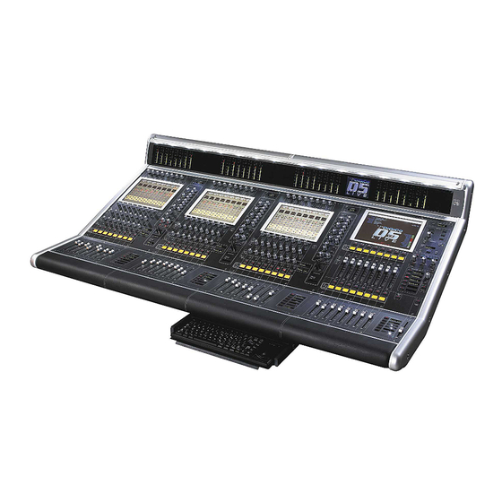
digico D5 Live Skrócona instrukcja obsługi - Strona 9
Przeglądaj online lub pobierz pdf Skrócona instrukcja obsługi dla Mikser digico D5 Live. digico D5 Live 18 stron. Digital console

Synchronisation Connections .....................................................
When the D5 is used with only analogue siganls connected to both inputs and outputs
syncronisation does not need to be considered. In this case the mixer is run from its own internal
master or Optocore clock.
There are, in fact, two separate synchronisation systems which use different connections - the Sample
Word Clock (or Digital Sync) and the Timecode system (not usually used for conventional live sound
applications).
The issues surrounding synchronisation in a digital system are complex, and do not fall within the scope of
this manual, but this section gives a basic description of the console's different sync inputs and outputs.
Rack Module Inputs and Outputs ...............................................
The modules fall into two broad groups - those which carry only inputs or outputs, and those which carry
both input and output signals. Output modules must be installed in Output slots, while Input and I/O
modules must be installed in Input slots.
Digital Sync Connections .............................................................
Using current firmware (V1), if the Optocore® optical system is in use to connect to the stage rack(s) then
the Optocore clock MUST be selected as clock source in the console software.
The following notes are relevent if the system is being used with only Coax MADI connections in use. The
console can be configured to use any of its digital inputs as a sync or word-clock source. The sync source
is set up when the console is installed, but can be reconfigured in the Worksurface Master section.
External Sync via Worksurface Rear Panel...................................
The Worksurface rear panel has connectors for Word Clock and Video Sync, either of which can be used
as the master sync source. Although the Video Sync input carries only a frame boundary signal, the
console generates a full digital word-clock from it.
The Worksurface has an input for AES/EBU. If connected to outputs from other digital audio units or
house clock, you can choose to sync the console to these inputs. The AES/EBU input acts as word-clock
even if there is no actual audio present (null signal). Note a signal connected to this rear panel cannot act
as an audio input to the console - this can only be used for sync.
External Sync via an I/O Rack........................................................
Any digital audio input can be selected as the digital sync master for the console, and each rack unit also
has a separate Word Clock output - these are located on the Rack Control Panel. See the Rack section
for more information.
Timecode Connections ................................................................
(not Normally used on the D5 for conventional Live use)
With appropriate optional software, the console can slave to external timecode, and generate it's own
timecode outputs. All timecode connections are made via the Worksurface rear panel, which has input and
output connections for LTC (SMPTE), MIDI timecode, and Sony 9-pin (RS422). The MIDI and 9-pin
systems also provide Machine Control inputs and outputs.
Page 9
