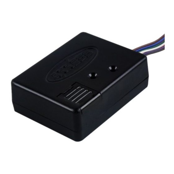
Axxess TRIGGER Instrukcja instalacji - Strona 7
Przeglądaj online lub pobierz pdf Instrukcja instalacji dla Elektronika samochodowa Axxess TRIGGER. Axxess TRIGGER 19 stron.

Mode 6: Active edge pulse generator
Description: Allow the capability of making an input signal a pulse signal.
Connections:
Interface wiring
Pin 4 (Pink)
Pin 6 (Green)
Pin 7 (Red)
Pin 8 (Blue)
Pin 9 (Brown)
Pin 10 (Gray)
Mode 7: Turn-off delay
Description: When the output is turned off, the pin 8 will stay active for two
additional seconds.
Connections:
Interface wiring
Pin 2 (Purple)
Pin 3 (White)
Pin 4 (Pink)
Pin 6 (Green)
Pin 7 (Red)
Pin 8 (Blue)
Pin 9 (Brown)
To
Ground
Negative pulsed output (500 mA max)
Negative pulsed output (500 mA max)
Positive pulsed output (2 amp max)
Positive input (use only one)
Negative input (use only one)
To
Ground
Ground
Ground
Negative delay turn-off output (500 mA max)
Negative delay turn-off output (500mA max)
Positive delay turn-off output (2 amp max)
12 volt output
