FIAMA F1X502SSI Instrukcja użytkowania i konserwacji - Strona 4
Przeglądaj online lub pobierz pdf Instrukcja użytkowania i konserwacji dla Monitor FIAMA F1X502SSI. FIAMA F1X502SSI 8 stron. Display unit with microprocessor
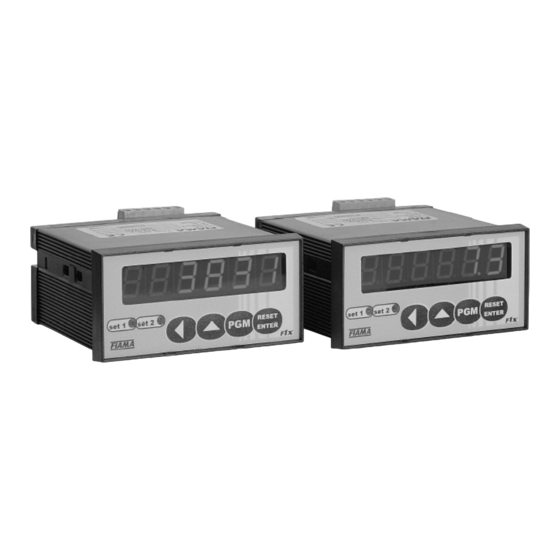
F1X5_SSI
Display unit with microprocessor
h) The instrument contains components sensitive to electrostatic charge, therefore the handling of the
electronic cards in it must be carried out with the appropriate devices, with the aim of avoiding permanent
damage to the very components.
Power supply
a) Before connecting the instrument verify that the power voltage is within the permitted limits indicated on the
plate.
b) Carry out electrical connections with the instrument disconnected.
c) For the instruments and sensors supply, beforehand create a supply line separated from the power line: if
necessary use an isolating transformer.
d) The supply line must provide a sectioning device with fuses upstream the instruments and must not be
used to control relays, contactors etc.
e) If the network voltage is seriously disturbed (switching of power groups, motors, inverters, welders etc.)
use the appropriate filters.
f) If an earth connection is required, make sure that the equipment is provided with a good earth installation:
voltage between neutral and earth <1V and resistance < 6 Ohm.
Connection of inputs and outputs
a) Physically separate the input cables from the supply cables, the output cables and from the power
connections; use shielded twisted pair cables, with display unit connected to ground in one point only .
b) Connect the setting and alarm outputs (contactors, solenoid valves, motors, electric fans, etc.) by
assembling RC groups (resistance and capacitor in series) parallel to inductive loads working in AC mode.
Assembly of the instrument
For a correct installation of the instrument, follow the procedure outlined below:
1. Insert the instrument in the specific cut-out.
2. Screw the screw onto the fixing block.
3. Hook the block to the instrument by means of the gains
4. Block the instrument by screwing the screws of the two blocks.
5. After that, make the electrical connections.
To assemble several instruments side-by-side, make sure axle bases are correct, as shown in the drawing.
Dimensions A and B can be read in the overall dimensions indicated in the manual.
Pag. 4/4
Date:13/01/16
F1X_SSI_ing.doc