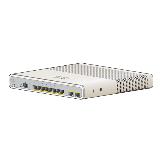
Cisco 2960-C Instrukcja instalacji - Strona 4
Przeglądaj online lub pobierz pdf Instrukcja instalacji dla Przełącznik Cisco 2960-C. Cisco 2960-C 37 stron.
Również dla Cisco 2960-C: Podręcznik dla początkujących (25 strony)

Powering the Switch
•
•
•
•
•
•
•
•
Equipment That You Supply
You might need this equipment to install the switch:
•
•
Box Contents
The switch getting started guide on Cisco.com describes the box contents. If any item is missing or
damaged, contact your Cisco representative or reseller for support.
Powering the Switch
Before installing the switch in a rack, on a desk, a shelf, or a wall, you should power on the switch and
verify that it passes POST.
Power the switch:
Catalyst 2960CPD-8PT-L and 2960CPD-8TT-L
•
•
Catalyst 3560-C and 2960-C Switch Hardware Installation Guide
2-4
Temperature around the unit does not exceed 113°F (45°C).
If the switch is installed in a closed environment or in a multirack assembly, the temperature around
it might be greater than normal room temperature.
Humidity around the switch must not exceed 95 percent.
Altitude at the installation site must not be greater than 10,000 feet (3,049 meters).
Do not place any items on the top of the switch.
Do not wall-mount the switch with its front panel facing up. Following safety regulations,
wall-mount the switch with its front panel facing down or to the side to prevent airflow restriction
and to provide easier access to the cables.
Clearance to the switch front and rear panels meets these conditions:
–
You can easily read the front-panel LEDs.
Access to ports is sufficient for unrestricted cabling.
–
The AC power cord can reach from the AC power outlet to the connector on the switch
–
rear panel.
For 10/100 and 10/100/1000 fixed ports, cable lengths from the switch to connected devices are not
more than 328 feet (100 meters).
For cable lengths for small form-factor pluggable (SFP)-module connections, see the
Connectors" section on page B-2
Number-2 Phillips screwdriver
Drill with a #27 drill bit (0.144-inch [3.7 mm])
Connect a 10/100/1000 uplink port to a PoE or PoE+ switch, such as a Catalyst 3750-X.
Or
Plug the auxiliary power adapter cord into the switch AUX power connector and into an AC power
outlet.
and the module documentation.
Chapter 2
Switch Installation
"SFP Module
OL-23803-02
