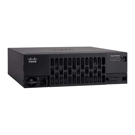
Cisco 4500-M Instrukcja wymiany - Strona 13
Przeglądaj online lub pobierz pdf Instrukcja wymiany dla Przełącznik Cisco 4500-M. Cisco 4500-M 16 stron. Upgrading memory
Również dla Cisco 4500-M: Instrukcja instalacji (18 strony), Instrukcja aktualizacji (24 strony)

Replacing Connections to the Router
Take the following steps to make the final connections to the router:
Warning
Step 1
Step 2
Step 3
Warning
or spade-type with upturned lugs. These terminations should be the appropriate size for the wires
and should clamp both the insulation and conductor.
Warning
Warning
using the appropriate lugs at the wiring end, as illustrated. The proper wiring sequence is ground to
ground, positive to positive (line to L), and negative to negative (neutral to N). Note that the ground
wire should always be connected first and disconnected last.
Warning
handle and reinstate power by moving the handle of the circuit breaker to the ON position.
Step 4
Step 5
This completes the power supply replacement procedure.
Read the installation instructions before you connect the system to its power source.
Replace all network connections.
If you have an AC-powered system, plug the system power cord into a 3-terminal,
single-phase power source that provides power within the acceptable range
(100–240 VAC, 50–60 Hz, 3.0–1.5 A).
If you have a DC-powered system, rewire the DC-input power supply (40 to 72 VDC) to
the terminal block using 14 AWG copper wires. The proper wiring sequence is ground to
ground, positive to positive, and negative to negative. (See Figure 10.)
When stranded wiring is required, use approved wiring terminations, such as closed-loop
This unit is intended for installation in restricted access areas.
The illustration shows the DC power supply terminal block. Wire the DC power supply
After wiring the DC power supply, remove the tape from the circuit breaker switch
Turn ON the system power switch. The power LED on the front panel of the router should
go ON. )
Check the OK LED on the right side of the front panel to verify that it goes ON after a
few seconds delay when booting. If you have problems, see the section "Troubleshooting
the Power Supply Installation" and the section "Cisco Connection Online."
Replacing Connections to the Router
Replacing the Cisco 4000 Series Power Supply
13
