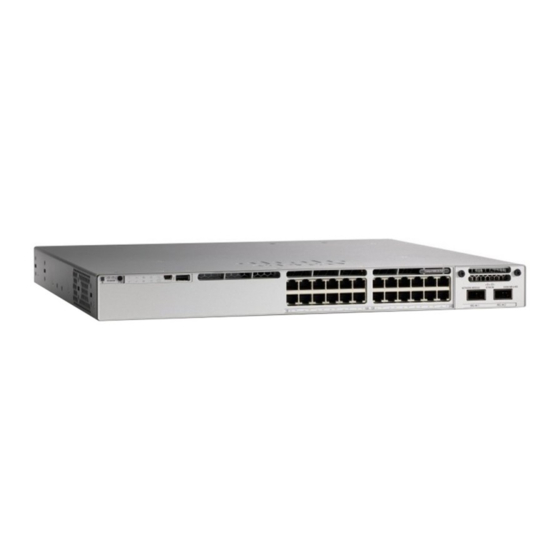
Cisco C3850-NM-4-1G Instalacja - Strona 14
Przeglądaj online lub pobierz pdf Instalacja dla Przełącznik Cisco C3850-NM-4-1G. Cisco C3850-NM-4-1G 17 stron.
Również dla Cisco C3850-NM-4-1G: Podręcznik (15 strony)

Installing SFP and SFP+ Modules
Note
Step 5
Grasp the captive screws, and carefully slide it out of the slot.
Step 6
Install a replacement network module or a blank module in the slot.
Step 7
Place the module that you removed in an antistatic bag or other protective environment.
Installing SFP and SFP+ Modules
Before You Begin
You must have an installed network module to use SFP and SFP+ modules (except for the Catalyst
WS-C3850-12S and WS-C3850-24S). The downlink ports on the Catalyst WS-C3850-12S and WS-C3850-24S
switch models support standard SFP modules, and the downlink ports on the Catalyst WS-C3850-12XS and
WS-C3850-24XS switch models support standard SFP+ modules.
See the switch release notes on Cisco.com for the list of supported SFP and SFP+ modules. Use only supported
SFP modules on the switch. For the latest information about supported SFP and SFP+ modules, refer to the
Cisco Transceiver Modules Compatibility Information at
ps5455/products_device_support_tables_list.html
For information about installing, removing, cabling, and troubleshooting SFP modules, see the module
documentation that shipped with your device.
Observe these precautions:
Class 1 laser product. Statement 1008
Warning
• Do not remove the dust plugs from the SFP modules or the rubber caps from the fiber-optic cable until
• Removing and installing an SFP module can shorten its useful life. Do not remove and insert any SFP
• To prevent ESD damage, follow your normal board and component handling procedures when connecting
• When you insert several SFPs in multiple switch ports, wait for 5 seconds between inserting each SFP.
Catalyst 3850 Switch Hardware Installation Guide
14
The C3850-NM-8-10G module is held secure in the switch by only one jackscrew. This screw also
helps to eject the module from its connector interface. Before the module can be removed completely,
the screw must be unscrewed all the way out. When removing the screw, a spring pushes the module
out when the screw is completely disengaged. Ensure that you hold the module securely until it is
completely removed.
you are ready to connect the cable. The plugs and caps protect the module ports and cables from
contamination and ambient light.
module more often than is necessary.
cables to the switch and other devices.
This will prevent the ports from going into error disabled mode. Similarly, when you remove an SFP
from a port, wait for 5 seconds before reinserting it.
Installing a Network Module
http://www.cisco.com/en/US/products/hw/modules/
OL-26779-05
