Fiber Options S711D Instrukcja obsługi - Strona 10
Przeglądaj online lub pobierz pdf Instrukcja obsługi dla System mikrofonowy Fiber Options S711D. Fiber Options S711D 14 stron. Universal data

RS485 APPLICATION NOTES
C. Data IN LED should be OFF, since there is no input
copper connection made.
D. Level /Loss should be green to off (but not red), indi-
cating that sufficient optical power is being received.
After the test has been performed at one end, swap switch
positions and connectors to perform the test on the other
end. Having done this, you have proven that the copper-
in-to-fiber-to-copper-out conversion is working in both
directions.
LED OPERATION
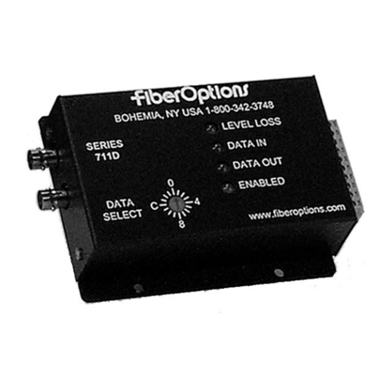
The S711D has 4 LED indicators that are very useful in
describing the current state of operation, as well as the cur-
rent status of data flow and fiber optic signal strength.
These indicators are LEVEL/LOSS
OUT, and ENABLED. They function as follows:
LEVEL/LOSS
TM
: This LED is useful for indicating the rela-
tive optical signal strength at the fiber optic receiver. When
sufficient optical power is being received, the LED shines
green. As the optical power is decreased, as happens
through long fiber runs, splices, or connections, the inten-
sity of the LEVEL/LOSS
of the S711D's sensitivity range has been reached. At this
point the LED will appear OFF. If any additional optical
attenuation is introduced, the LEVEL/LOSS
bright RED, indicating an insufficient amount of optical
8
CONTINUED
, DATA IN, DATA
TM
LED will diminish until the limit
TM
TM
LED will turn
power is being received. All data will default to it's failure
state level to eliminate bus contention.
DATA IN: The DATA IN LED indicates the level of the data
being input to the S711D over copper. A GREEN LED indi-
cates a logic HIGH is present on the copper inputs. A YEL-
LOW indication indicates a logic LOW is present on the
copper. No color (OFF) indicates a tri-state or high imped-
ance input. This can therefore be used to determine the
resting state of your equipment and, in the RS485 states,
verify that a tri-state is being detected properly. Unlike
most competing units, the S711D has special circuitry to
capture data transitions and make them visible on the
LEDs.
High-speed bursts of activity, previously unde-
tectable by standard LED circuits, can easily be seen by
this special circuitry.
DATA OUT: The DATA OUT LED functions identically to
the DATA IN LED except that the LED represents data that
is being output from the unit. This LED has the same high-
speed capture circuitry described in the DATA IN section.
ENABLED: This LED has three states. GREEN, to indi-
cate a valid mode has been selected, RED to indicate an
invalid mode (spare or test-mode) has been selected, or
FLASHING RED/GREEN to indicate that NO mode has
been selected.
Table 20 provides a convenient summary of the LED dis-
play functions.
S711D & S7711D Instruction Manual
