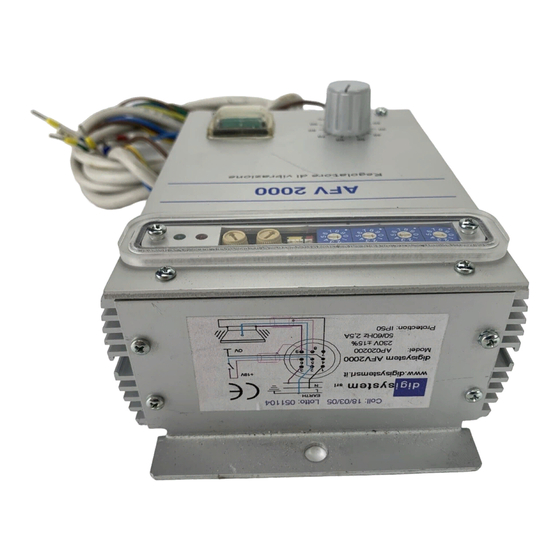
DIGISYSTEM AP00010G Instrukcja obsługi - Strona 5
Przeglądaj online lub pobierz pdf Instrukcja obsługi dla Zasilanie DIGISYSTEM AP00010G. DIGISYSTEM AP00010G 9 stron.

WIRING TABLE
PIN REF.
SIGNAL DESCRIPTION
GROUND CONNECTION
M3-6
M3-5
MAINS INPUT (NEUTRAL)
M3-4
MAINS INPUT (PHASE)
M3-3
GROUND and SHIELD CONNECTION
M3-2
OUTPU SUPPLY FOR VIBRATOR
M3-1
OUTPU SUPPLY FOR VIBRATOR
M2-9
CURRENT REFERENCE (0-20mA)
M2-8
VOLTAGE REFERENCE (0-5V)
M2-7
POTENTIOMETER CURSOR
M2-6
POTENTIOMETER MINIMUM
M2-5
POTENTIOMETER MAXIMUM
M2-4
0V INSULATED FOR REMOTE
COMMANDS
M2-3
REMOTE START-STOP COMMAND
M2-2
OUTPUT POWER SUPPLY OK
M2-1
+18V INSULATED FOR REMOTE
COMMANDS
Note:
The guts of the vibrator must be grounded with a appropriate wire.
Before supplyng the device verify that there are not ground dispersions on
wires connecting the power supply to the vibrator; The power supply will be
damaged if one of the two output wires is grounded.
Downloaded from StockCheck.com
WIRE SECTION
mmq
3x1
3x1
3x1
3x1
shielded
3x1
shielded
3x1
shielded
0,35
0,35
0,35
0,35
0,35
0,35
0,35
0,35
0,35
5
CONNECT TO:
EARTH
230 Vac
230 Vac
VIBRATOR (if provided)
VIBRATOR COIL
VIBRATOR COIL
VOLTAGE REF.
CURSOR
COUNTERCLOCKWISE
CLOCKWISE
