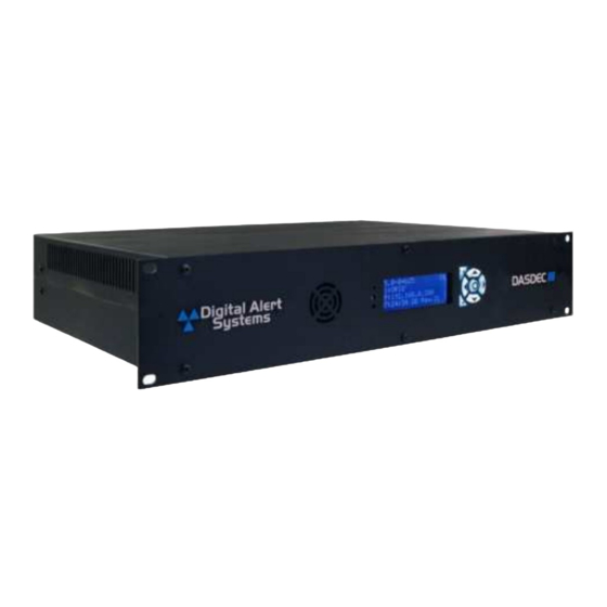
Digital Alert Systems DASDEC-III Instrukcja instalacji sprzętu - Strona 8
Przeglądaj online lub pobierz pdf Instrukcja instalacji sprzętu dla System bezpieczeństwa Digital Alert Systems DASDEC-III. Digital Alert Systems DASDEC-III 16 stron.

Digital Alert Systems
Back Panel
All hardware connections are provided on the device's back panel.
Program Audio In/Out
Radio 1 & 2
4
th
Audio In
(Option)
Keyboard/Mouse
AC Power
Back Panel View of the DAS3-GX or DAS3-EX with DAS3-AES and EXP-2NICGIG options
The image above includes the Dual Port Gigabit Ethernet Expansion and AES Audio Options. Not all
DASDEC-III
devices
will contain the same rear connectors.
The Expansion Slots are used for optional additional Network Interfaces and additional EAS Audio input
hardware. Expansion hardware is only available with the DAS3-EX or the DAS3-GX.
Installation
The DASDEC-III frame mounts in an EIA-compliant equipment rack by means of four rack screws fastened
through the front mounting ears.
For safe, long-term reliability:
•
Ensure the ambient air temperature surrounding the EAS device is within the product's
specified operating temperature range.
• Maintain adequate ventilation within the rack.
• Ensure that adequate space exists on all sides of the frame for sufficient airflow. It is
recommended a 1RU space be maintained between equipment, to avoid the transfer of heat
between devices.
• Ensure the location of the EAS device is accessible, dry, and free of dust.
Rack Units
2RU
Radio Antennas
The EAS device can be equipped with two or three (optional) internal radio receivers and connect using
Revision 1.0
GPI/O
Radio 3
(Option)
VGA
HDMI w/Audio
Dual USB 2.0
Height
3.50" (8.89 cm)
12.0" (30.48 cm) 19.0" (48.26 cm) 15 lbs (6.8 kg)
DASDEC-III Hardware/Installation Guide
AES Audio In/Out
(Optional)
Power
Main Network
Dual USB 3.0
Depth
Width
Secondary Audio Input
Expansion Slot
Dual Network
Serial Port
(Option)
Weight
Page 8 of 16
