Crestron 6508043 Instrukcja instalacji
Przeglądaj online lub pobierz pdf Instrukcja instalacji dla Kontroler Crestron 6508043. Crestron 6508043 2 stron. Shutter motor controller
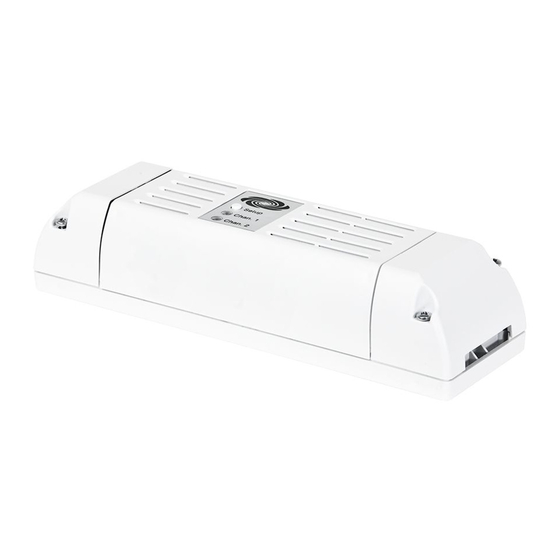
CLCI-MCEX
Shutter Motor Controller
Installation Guide
Description
The Crestron
®
CLCI-MCEX is a motor controller that provides open and close control of
one shade or shutter motor. The CLCI-MCEX has outputs for raise/open and lower/close
control.
Its ultra-slim design allows it to be installed in the ceiling, either next to or near the motor.
Powered by infiNET EX
technology, the CLCI-MCEX communicates wirelessly with the
®
control system, making it perfect for both new and retrofit applications. Install an in-line
switch to provide local control of the shade or shutter motor.
Additional Resources
Visit the product page on the Crestron website (www.crestron.com)
for additional information and the latest firmware updates. Use a QR
reader application on your mobile device to scan the QR image.
Important Notes
CAUTION: Observe the following points:
• Install the CLCI-MCEX only on 10 A branch circuits.
• Install using wires that are 1 mm
IEC 60227-5 and local electrical codes.
• Use the CLCI-MCEX with loads that have a power factor of 0.50 or greater.
• To meet radiated emissions requirements, ensure that 3 feet (1 meter) of wiring
leading to and from the CLCI-MCEX is straight and that there are no loops in the
wiring.
NOTE: Observe the following points:
• Codes: This product must be installed by a licensed electrician and in
accordance with all local and national electrical codes.
• Wiring: The CLCI-MCEX requires a neutral connection to operate.
• Wiring: Use copper wire only. For supply connections, use wires rated at least
75 °C.
• Motor Type: For use with a permanently installed motor.
• Temperature: For use where temperatures are between 0° and 40 °C
(32° and 104 °F).
• Transportation and Storage: Transport and store this device when temperatures
are between -25° and 60 °C (-13° and 140 °F).
• Spacing: If mounting one device above another, leave at least 115 mm (4-1/2 in)
vertical space between them.
Installation
WARNING: To avoid fire, shock, or death, turn off the power at the circuit breaker or
fuse and test that the power is off before wiring!
Install the CLCI-MCEX:
1. Turn off the power at the main circuit breaker.
WARNING: The device should be mounted in a well-ventilated and dry area.
2. Identify the installation location for the CLCI-MCEX.
3. Remove the end caps from the device by unfastening the two screws shown.
Unscrew
and remove.
4. Loosen the strain relief clamp screw and rotate the clamp to the side for wiring.
L N G G N L L R
Loosen the screw.
5. To mount the device (optional), use two M3 X .05 screws (not included).
Mounting Screw Locations
to 2.5 mm
and that comply with
2
2
Unscrew
and remove.
(Do NOT remove.)
6. Wire the device as shown in the illustration in the "Wiring" section.
CAUTION: Use with wires that are 1 mm
7. Tuck the wires under the strain relief clamps, and tighten the clamp screws. The
jacketed cable must be clamped under the strain relief clamps.
L N G G N L L R
Tighten the screws.
8. Replace the end caps.
9. With the device still accessible, turn on the main circuit breaker.
Wiring
WARNING: To avoid fire, shock, or death, turn off the power at the circuit breaker or
fuse and test that the power is off before wiring!
Wire the CLCI-MCEX and a remote switch.
SW2 and N to
motor close
in NET EX
communication to
control system
L N G G N L L R
Live (brown)
AC input
Neutral (blue)
from
breaker
Earth
(green/yellow)
Earth
(green/yellow)
Neutral (blue)
AC to
next
Live (brown)
device
NOTE: The jacketed cable must be clamped under the clamping bar.
Remote Maintained (Single Switch)
Live
Remote
Remote Maintained (Multiway)
Live
Remote Momentary (Multiway)
Live
Remote
to 2.5 mm
.
2
2
To motor
SW1 and N to
motor open
SW2 N SW1 N
Remote (brown)
Live
230 VAC
(brown)
maintained or
momentary
switch
Remote Maintained (Multiway)
Live
Remote Momentary (Single Switch)
Live
Remote
Remote
Remote