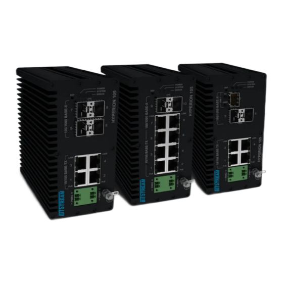
Bitstream HYPERION-105 Instalacja i skrócona instrukcja obsługi - Strona 3
Przeglądaj online lub pobierz pdf Instalacja i skrócona instrukcja obsługi dla Przełącznik Bitstream HYPERION-105. Bitstream HYPERION-105 6 stron.

Quick start manual, a detailed manual is on the enclosed CD or www.bitstream.com.pl
The table shows the lay-out of particular signals for RJ-45 connectors
Status signaling of Ethernet interfaces
Each Ethernet port is equipped with two signaling diodes.
The LED on the left indicates PoE is working:
•
green PoE / PoE + with the inserted cable delivered power in PoE (up to 15W) or PoE + (up to 30W)
•
yellow PoE ++ with inserted cable supplied power in PoE ++ (60W) or High Power PoE (90W)
standard
•
yellow blinking when the cable is removed - force mode (permanently switched on the power supply of
a given port bypassing the PoE standard). After inserting the cable with the PoE receiver on the other
side, the LED lights up green. In this mode, the power delivered to the receiver is limited to 15W per port.
The LED on the right indicates link :
LED Link-act
• LED 10M - yellow link 10Mbps (for activity - blinking)
• LED 100M - green link 100Mbps (for activity - blinking)
I/O interface connector description - (option)
The arrangement of individual signals for the IO contacts is shown in the table below
Interface
IN
OUT1
OUT2
REV.
1.14
Connector type: RJ-45 (PE1-PE8) Ethernet 10/100Mbit/s
1 (white/orange)
RXAn
2 (orange)
RXBn
3 (white/green)
TXAn
6 (green)
TXBn
IN COM NC1
Rys. 1. Appearance and numbering of the I/O connector pins
Destiny
Potential free input
Relay output 1
Relay output 2
SHORT USER MANUAL HYPERION-105
Channel transmitter
Channel receiver
COM
NO1 NC2
COM
Description of leads
IN - input contact,
COM - Base contact
NC1 - output normally shorted to COM
NO1 - output normally open to COM
COM - Base contact
NC2- output normally shorted to COM
NO2 - output normally open to COM
COM - Base contact
.
NO2
2021.03.31
3/6
