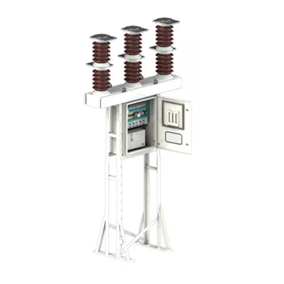
Siemens 3AF 01 Instrukcja obsługi - Strona 4
Przeglądaj online lub pobierz pdf Instrukcja obsługi dla Urządzenia przemysłowe Siemens 3AF 01. Siemens 3AF 01 24 stron. Outdoor vacuum switchgear

2. Technical data
2.1
Type spectrum
2.1.1
Type designation
3AF 01 vacuum circuit-breakers are identified by a
machine-readable product designation made up of a
series of numbers and letters, whose first 8 places can be
found on the name plate of the circuit-breakers. The
design code stated on the name plate together with the
machine-readable product designation provides a full
description of the circuit-breaker. The figure below shows
what the individual places of the basic machine-readable
product designation stand for:
3
A
F
0
1
4
3
Besides the basic machine-readable product designation
of the circuit-breaker stated on the name plate (Fig. 2); it
also contains the following information.
s
Type designation
Serial number
Rated voltage / Frequency
Rated s.c. breaking current
Rated light
imp. with. voltage
•
Purchase Order No. & Date
Rated operating duty
Made in India
Fig. 2: Name plate
For abbreviations of rated characteristics, refer Table 1
below.
The name plate, is located on the mechanism housing of
the circuit-breaker.
2.1.2
Rated data
Type
Rated
Rated
designation voltage
short-circuit
making current breaking current
U in kV
I
ma
3AF 01 42
36
3AF 01 43
36
3AF 01 44
36
3AF 01 45
36
3AF 01 47
36
Table 1: 3AF 01 Technical Data
2
Basic designation &
Rated voltage,
Rated short circuit
breaking current
Rated normal
current
Electrical
autoreclosing
-
4
Design code
Year of manufacture
Rated normal current
Rated s.c. duration
Weight
03-95307-001
Rated
short-circuit
short-circuit
in kA
I
in kA
sc
66
26.3
66
26.3
66
26.3
62.5
25
62.5
25
NOTE
In the event of any queries, state the type designation,
design code, year of manufacture and the serial
number.
2.1.3
Dimensions and weights
The dimensions of the vacuum circuit-breaker are shown
in the relevant drawings, which can be ordered through
your Siemens office.
The weight can be found on the breaker rating plate, in
Fig. 2; or in the relevant drawing.
2.2
Characteristic values
Definitions:
Opening time = the interval of time between the
initiation of the opening operation and the instant when
the contacts separate in all poles.
Arcing time = the interval of time between the instant of
the first initiation of an arc and the instant of final arc
extinction in all poles.
Break time = the interval of time between the initiation
of the opening release and the instant of final arc
extinction in all poles. (= opening time + arcing time).
Close-open time = the interval of time (in a make-break
operating cycle) between the instant when the contacts
touch in the first pole in the closing process and the
instant when the arcing contacts separate in all poles in
the subsequent opening process.
Dead time = The interval of time between final arc
extinction in all poles in the opening operation and the
first re-establishment of current in any pole in the
subsequent closing operation.
Closing time = the interval of time between the
initiation of the closing release and the instant when the
contacts touch in all poles.
Rated
Rated
Rated power
current
frequency
duration
withstand voltage withstand voltage distance
t
in s
I
in A
in kV
th
n
3
1250
3
1600
3
2000
3
1600
3
2000
Rated lightning
impulse
U
in kV
w
70
170
70
170
70
170
70
170
70
170
Pole
Weight
centre
(approx.)
in mm
in kg
725±5
650
725±5
650
725±5
650
725±5
650
725±5
650
