Siemens SINAMICS G130 Instrukcja obsługi - Strona 23

Przeglądaj online lub pobierz pdf Instrukcja obsługi dla Urządzenia przemysłowe Siemens SINAMICS G130. Siemens SINAMICS G130 28 stron. Line filter
Również dla Siemens SINAMICS G130: Instrukcja obsługi (24 strony), Instrukcja obsługi (26 strony), Instrukcja obsługi (46 strony), Instrukcja obsługi (24 strony), Instrukcja obsługi (31 strony), Instrukcja obsługi (30 strony), Instrukcja obsługi (28 strony), Instrukcja obsługi (30 strony), Instrukcja obsługi (22 strony), Instrukcja obsługi (30 strony), Instrukcja obsługi (34 strony), Instrukcja obsługi (46 strony), Instrukcja obsługi (26 strony), Instrukcja obsługi (26 strony), Instrukcja obsługi (28 strony), Instrukcja obsługi (42 strony), Instrukcja obsługi (46 strony), Instrukcja obsługi (24 strony), Instrukcja obsługi (24 strony), Instrukcja obsługi (30 strony), Instrukcja obsługi (42 strony), Instrukcja obsługi (38 strony), Instrukcja obsługi (46 strony), Instrukcja obsługi (28 strony), Instrukcja obsługi (22 strony), Instrukcja obsługi (24 strony)
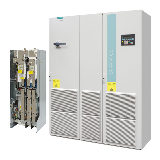
Siemens SINAMICS G130 Instrukcja obsługi
4.3.4

X521 three-phase line supply voltage sensing up to 100 V (phase-to-phase)

Table 4- 4
Max. connectable cross-section: 1.5 mm²
NOTICE
Destruction of the VSM10 as a result of a terminal assignment which is not permissible
The VSM10 has two terminal strips, X521 and X522, to sense the three-phase line supply
voltage. A terminal assignment which is not permissible results in the module being
destroyed.
• Use just one of the two terminal strips.
• Only connect voltages to terminal strip X521 up to a maximum 100 V (phase-to-phase)
• Only connect voltages to terminal strip X522 up to a maximum 690 V (phase-to-phase)
Note
Connection sequence
The phases must be connected to the VSM10 with the same sequence as that of the Power
Module.
Voltage Sensing Module 10 (VSM10)
Operating Instructions, 11/2017, A5E02142235A
Terminal block X521
Terminal
1
2
3
via a transformer.
directly.
Designation
Technical specifications
Phase voltage U
Connection to the voltage sensing for medium-
voltage networks via a safe electrically isolated
Phase voltage V
transformer
Phase voltage W
Resistance to neutral point: each ∼500 kΩ
Insulation resistance, neutral point - ground when
the jumper is not inserted: >10 MΩ
Electrical installation
4.3 Interface description
21