Siemens SINAMICS G130 Instrukcja obsługi - Strona 22

Przeglądaj online lub pobierz pdf Instrukcja obsługi dla Urządzenia przemysłowe Siemens SINAMICS G130. Siemens SINAMICS G130 30 stron. Line filter
Również dla Siemens SINAMICS G130: Instrukcja obsługi (24 strony), Instrukcja obsługi (26 strony), Instrukcja obsługi (46 strony), Instrukcja obsługi (24 strony), Instrukcja obsługi (31 strony), Instrukcja obsługi (30 strony), Instrukcja obsługi (28 strony), Instrukcja obsługi (30 strony), Instrukcja obsługi (22 strony), Instrukcja obsługi (28 strony), Instrukcja obsługi (34 strony), Instrukcja obsługi (46 strony), Instrukcja obsługi (26 strony), Instrukcja obsługi (26 strony), Instrukcja obsługi (28 strony), Instrukcja obsługi (42 strony), Instrukcja obsługi (46 strony), Instrukcja obsługi (24 strony), Instrukcja obsługi (24 strony), Instrukcja obsługi (30 strony), Instrukcja obsługi (42 strony), Instrukcja obsługi (38 strony), Instrukcja obsługi (46 strony), Instrukcja obsługi (28 strony), Instrukcja obsługi (22 strony), Instrukcja obsługi (24 strony)
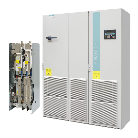
Siemens SINAMICS G130 Instrukcja obsługi
Electrical installation
4.2 Interface description
NOTICE
Damage to motor in the event of incorrectly connected KTY temperature sensor
A KTY temperature sensor connected with incorrect polarity cannot detect if the motor
overheats. Overheating can cause damage to the motor.
• Connect a KTY temperature sensor with the correct polarity.
NOTICE
Overheating of the motor through jumpering the temperature sensor connections
Jumpering of the temperature sensor connections "+ Temp" and "- Temp" results in
incorrect measurement results. Damage to the motor can result if the overheating is not
detected.
• When using several temperature sensors, separately connect the individual sensors to
NOTICE
Overheating of the motor through cables with too high a resistance
Cable length and cable cross-section can falsify the temperature measurement (10 Ω cable
resistance for a PT100 can falsify the measurement result by 10%). Damage to the motor
can result if the overheating is not detected.
• Use only cable lengths ≤ 300 m.
• For cable lengths >100 m, use cables with a cross-section of ≥1 mm
NOTICE
Device failure as a result of unshielded or incorrectly routed cables to temperature sensors
Unshielded or incorrectly routed cables to temperature sensors can result in interference
being coupled into the signal processing electronics from the power side. This can result in
significant disturbance of all signals (fault messages) up to failure of individual components
(destruction of the devices).
• Only use shielded cables as temperature sensor cables.
• If temperature sensor cables are routed together with the motor cable, use separately
• Connect the cable shield to ground potential through a large surface area.
• Recommendation: Use suitable Motion Connect cables.
22
"+ Temp" and "- Temp".
shielded cables twisted in pairs.
.
2
Terminal Module 150 (TM150)
Operating Instructions, 04/2014, A5E03758735A