Siemens SIPART PS2 Instrukcja obsługi - Strona 16

Przeglądaj online lub pobierz pdf Instrukcja obsługi dla Urządzenia przemysłowe Siemens SIPART PS2. Siemens SIPART PS2 28 stron. Mounting bracket kit
Również dla Siemens SIPART PS2: Instrukcja instalacji (4 strony), Instrukcja instalacji (4 strony), Instrukcja instalacji sprzętu (30 strony), Opis techniczny (26 strony), Kompaktowa instrukcja obsługi (35 strony), Instrukcja instalacji zestawu (9 strony), Instrukcja instalacji (11 strony)
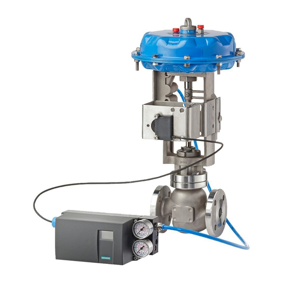
Siemens SIPART PS2 Instrukcja obsługi
Connecting
4.1 Connection safety note
NOTICE
Maximal values for terminals 41/42 and 51/52
The following maximum values concern only terminals 41, 42, 51, and 52:
• Maximum voltage:
• Maximum current:
• Maximum performance:
No safe separation between the terminals can be guaranteed.
NOTICE
Installing/connecting
Only qualified personnel is permitted to install and connect the mechanical limit switch
module.
NOTICE
To observe before connecting
Before you connect the mechanical limit switch module, observe the following conditions:
• Only qualified personnel is permitted to connect the mechanical limit switch module.
• Isolate all wires from power and make sure the device is truly isolated from power.
• Construct the cross-sectional area of the connection cables in such a way that it is
• Selected the wires on the basis of the following rule: The temperature at which the wires
• Operate the Ex-version only in intrinsically safe circuits with approved switching
NOTICE
Preparing the cables or stranded wires
1. Insulate the cables in such a way that the insulation is flush with the terminal when
2. Fit ferrules to the ends of stranded wires.
16
– Not Ex: AC 250 V or DC 24 V
– Ex: 30 V DC
– Not Ex: 4 A AC/DC
– Ex: 100 mA DC
– Ex: 750 mW
appropriate for the permitted current load.
are permitted to be used must be 25°C above the maximum ambient temperature.
amplifiers.
plugging in the wires.
SIPART PS2 with mechanical limit switch module
Operating Instructions (Compact), 04/2007, A5E01179056-01