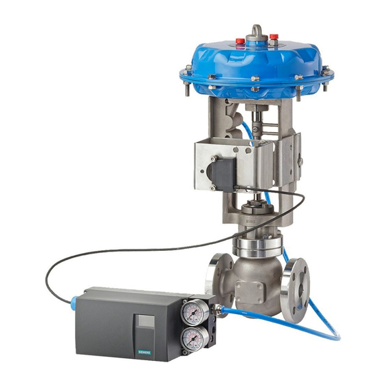
15900-796
14. Use the [+] and [-] buttons to move the valve to the mid-stroke position and release pushbuttons.
Use the valve travel indicator plate on the actuator yoke to locate mid-stroke. At mid-stroke, the
feedback lever should be approximately perpendicular to the actuator shaft.
15. Adjust slip clutch until display reads 50, +/-3.0. See Figure 10 for slip clutch location.
16. Press and hold [HAND] button to enter configuration mode; release button once display changes.
17. Verify that parameter 1 appears in the lower left corner of the display. If another parameter
number appears, press and release the [HAND] button until parameter 1 appears.
Note: To move backwards in the menu, press and hold [HAND] button and toggle
[–] minus button.
18. Verify that
appears in the display. If another parameter value appears, press and release the
[+] or [-] button until
19. Press [HAND] button to go to parameter 2.
20. Read the transmission gear ratio setting in the display: 33 or 90. If necessary, use [+] or [-] button
to change the value to actual gear ratio setting from steps 2 and 3 on page 9.
21. Press [HAND] button twice to go to parameter 4.
22. Press and hold [+] button to execute initialization process – release the button once the positioner
begins to move the valve.
23. Initialization is complete once display reads "Finish". If setup messages appear, refer to the
Possible Messages section of the Quick Setup Guide provided in the PS2 housing.
24. Press [HAND] button once.
25. Press and hold [HAND] button to exit configuration mode. Release button once display changes.
26. Press [HAND] button to enter "Auto" mode.
27. Test valve performance by changing the input signal.
28. As needed, modify other parameters to meet valve application specifications. The following
parameter names are those that are commonly adjusted.
"SCUR" – Change positioner Direct/Reverse action [rise/fall]
"YDIR" – Change action of LCD display and 4-20 ma feedback (if so equipped)
"YCLS" – Activate Tight Closing; full supply air supplied to one side of actuator
"YCDO" – Input signal threshold value for tight closing, bottom position
"YCUP" – Input signal threshold value for tight closing, top position
"PRST" – Parameter reset: Return all parameters to factory default values
29. If needed, refer to the SIPART PS2 manual (see the footnote on page 4) for complete installation,
configuration, and service information.
Once all setup steps are completed and the feedback arm moves freely for the entire stroke, make
any additional electrical connections.
appears.
8

