Siemens SIWAREX R Instrukcja obsługi - Strona 10
Przeglądaj online lub pobierz pdf Instrukcja obsługi dla Urządzenia przemysłowe Siemens SIWAREX R. Siemens SIWAREX R 38 stron. Mounting units for sb series
Również dla Siemens SIWAREX R: Instrukcja obsługi (34 strony)

Revision 09/04
1.4
Load-cell Dummies
Load cells are sensitive sensors. To protect them from damage, they should only be
handled as late as possible for installation and transport. During installation and
transport, these should be replaced by dummies or phantoms. Dummies can be
constructed as follows for example:
1. A replica of the mounting element using a welded construction.
A pipe or any other steel profile can be welded between two plates with the
respective hole format for the fastening bolts. The total height corresponds
to the mounting height of the mounting element. That is the most stable
and safe version. Rough mounting work can be performed.
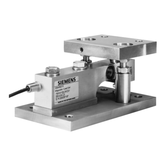
2. Using a SIWAREX R combination mounting unit.
The combination mounting units are supplied as completely assembled
units. The units are set at the approximate installation height for an
operational unit. Slight adjustments can be made during the installation.
1.5
Load Cell Handling
DANGER
Load cells and mounting units are not machine elements that are constructed
using standard safety factors. It is therefore absolutely necessary to prepare for the
potential danger with respective supports or other means of protection.
CAUTION
To protect against undesirable electrical current, such as static discharge that can
occur during welding or which can be caused by lighting for example, the load
cells should be bridged with highly flexible grounding cables
(e.g. SIWAREX R grounding cable 7MH3 701-1AA1).
SIWAREX R load cells may only be installed and connected by qualified personnel.
Load cells are precision components and are to be handled carefully. Pay special
attention during transport and assembly.
CAUTION
Mechanical jolts or dropping could irreparably damage the load cells.
Load cells are not to be carried by their connecting cables.
Document No.: A5E00353789B
General Conditions for Installation and Assembly
Page 10
