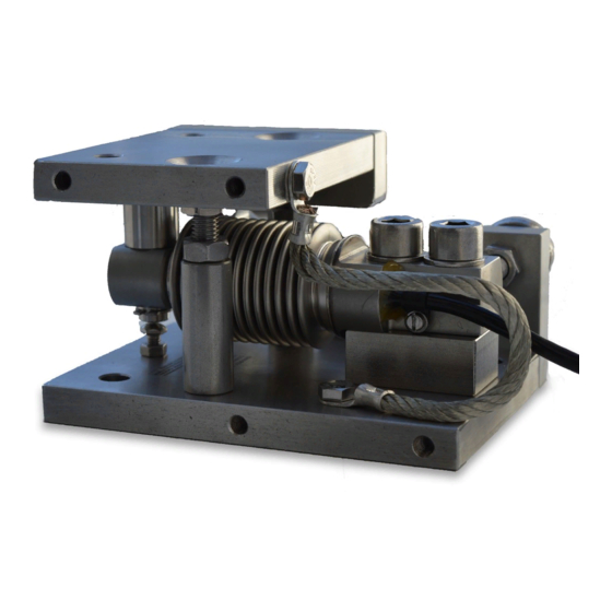
Siemens SIWAREX WL230 BB-S SA Instrukcja obsługi - Strona 14
Przeglądaj online lub pobierz pdf Instrukcja obsługi dla Urządzenia przemysłowe Siemens SIWAREX WL230 BB-S SA. Siemens SIWAREX WL230 BB-S SA 44 stron. Base plate and elastomer bearing bb-s sa
Również dla Siemens SIWAREX WL230 BB-S SA: Podręcznik (36 strony), Instrukcja obsługi (48 strony), Instrukcja obsługi sprzętu (50 strony)

Application planning
3.3 Load pick-up
3.3
Load pick-up
Mounting surfaces
The following requirements apply to the installation areas:
● The positional and angular deviations of the mounting areas to each other correspond to the
general tolerances for welded constructions in EN ISO 13920.
● Ensure that the foundations are absolutely firm and free of depressions. Mount the
installation elements in concrete foundations on evenly cast steel plates.
● The mounting surfaces must be vertical to the measuring direction and preferably in one
plane.
● A plane of ≤ 0.2 mm is required for the mounting surfaces.
More than three support points
For more than three support points, the load bearing implement is usually statically
indeterminate. With firm foundations and load bearing implements, the load is not evenly
distributed to all load cells. The same applies to unstable mounts such as a steel construction.
Two diagonal load cells bear the main load. The other load cells only support the load bearing
implement.
There are two ways to take this into consideration:
● Over-dimensioning of the load cells
● Height compensation of the support points
Over-dimensioning of the load cells
The rated load of the load cells is calculated such that with, for example, four support points the
entire weight can be borne by two load cells.
This also prevents an overload of the load cells if depressions in the foundation have to be
taken into consideration, e.g. for racks in the steel structure.
Height compensation of the support points
With this method, the output signals of all of the load cells are attuned to each other under a
load. To ensure that all of the load cells receive approximately the same load, use
compensation plates to compensate the heights. The compensation plates are positioned
between the bracket and top plate of the compact mounting unit.
The output signals of the individual load cells correspond to the load distribution.
Compensate for the differences in height as described in the section Compensation of height
with four or more support points (Page 25).
14
Operating Instructions, 03/2020, A5E47358100-AA
BB-S SA
