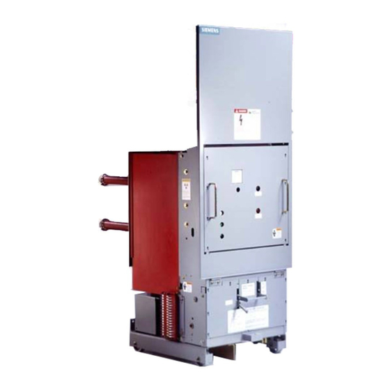
Siemens 15-FSV-750 Instalacja, obsługa i konserwacja - Strona 38
Przeglądaj online lub pobierz pdf Instalacja, obsługa i konserwacja dla Przełącznik Siemens 15-FSV-750. Siemens 15-FSV-750 48 stron. Vacuum circuit breakers fsv series and msv series

Vehicle/Description
Breaker Shaft 63 ,
Lob es Om itt ed
When Applied
With Screw
Type
Racking
Typically
1
1 to 2MM
(040" to 080")
'
2
Interlock
Pull Box
.
.
d
�;
: 1
1
Cub1cle Rail
_
Spnng P1n
_
_
-
:: � - -
•!---
- - - - - - - - - , � - --:·
-
Plunger
Figure 24a-1
Details of Closed Breaker Racking Interlock-Type FSV
As the push rod rises, its " m u s h room " headed append age,
within the breakers mechanism enclosure, causes the " i nter
lock" levers to rotate, elevating the "trip free push rod and cam".
Th i s cam encounters the "trip latch lever". and after typically
to 1 2m m ( 0 . 3 to 0 . 5 inches) of motion forces the mechan i s m ,
thru the "trip l a t c h leve r ", to the "trip free" state.
Contin ued full CCW rotation of the interlock bell c rank causes
the plunger to clear the c u bicle rai l a l lowing the "open trip free
b reaker" to be moved from the connected position.
The lower interlock bel l c rank i s returned to the plunger en
gaged positio n , fully c lockwise, by the action of double torsion
springs at each end of the bell crank. I t i s stopped and main
tained i n the position which ensu res full plunger engagement
by a s p ri n g p i n of suff i c ient length at the top of the plunger
which strad d le s the g u i d e bar and g u i d i ng channel.
1
Lever 64 3
(Clo sed Pos ition )
::J
1
,/',0
�_:
Levers
- , � - -
'
c
0
U::
Disconnect
Racking
Release
Handle
Torsion
Spring
.
.
'
I
Side View
Breaker Shaft 63 --""'
Lobes omitted
when applied to
Screw Type Racking
Typically
1
1 To 2 M M
(040" To 080") '
2
Interlock
Bell
Crank
Connection
Pull Box
Lever ,
Figure 24a-2
Details of Closed Breaker Racking Interlock-Type MSV
The b reaker may be pad locked i n an "open tri p-free" state.
Provision has been made for looping a padlock t h rough the
"racking release handle" and a stationary cover mounted an
gle. The position of the racking release handle at the point of
8
pad lock hole a l i g nment ensu res the breake r i s tri p-free yet the
plunger engages the rail-preventing b reaker movement.
Breaker Racking Interlock
(Screw Type)
Reference: Fig u res 24a
The racking i nterlock functions to maintain the breakers mech
anism i n a "trip free" state whenever the c i rcuit breake r i s
" released".
Lever 64 3
24b
&
Page 33
Racking
Release
Handle
c
0
U::
3
Link
Torsion
