Siemens TSM-1X Instrukcje instalacji - Strona 2
Przeglądaj online lub pobierz pdf Instrukcje instalacji dla Przełącznik Siemens TSM-1X. Siemens TSM-1X 4 stron. Intelligent test switch module with dual isolators
WIRING INSTRUCTIONS
CAUTION: Deactivate P2 circuit by either or
both of the following: Using the PMI, bypass the
circuit being modified, and/or physically
disconnect the circuit from the P2 source
Refer to the wiring diagrams in Figures 3 and 4 and
wire the TSM-1X to the device line of Desigo
FC2025/FC2050/FV2025/FV2050 and Cerberus
PRO FC922/FC924/FV922/FV924 Fire Alarm
Systems, Document ID A6V10315023.
Note: The recommended wire size is as follows:
18 AWG minimum
14 AWG maximum
POWER LIMITED WIRING FOR THE TSM-1X
TEST SWITCH MODULE
In compliance with NFPA 70—National Electrical
Code, all power limited fire protective signaling
conductors must be separated by a minimum of ¼
inch from all of the following items located within an
outlet box:
• Electric light
• Power
• Class 1 or non-power limited fire protective
signaling conductors
INSTALLATION
1. Remove the module from its protective bag.
Mount the TSM-1X in a user supplied, UL-
listed/recognized standard single gang
mounting box (minimum 3½ inches deep is
recommended). Refer to Figure 5.
2. Terminate all field wires to the TSM-1X as
required for your application. Refer to the
connection diagrams shown in Figures 3 and 4.
3. Insert the face plate and attach the cover plate
with the two screws provided. Refer to Figure 5.
NOTES:
1. In the device line, up to 30 of any
compatible devices in polarity insensitive
mode with 20 ohms max line resistance
can be isolated between two modules in
isolator mode in a Class A Style 6 wiring.
2. In the device line, up to 30 of any
compatible devices in polarity insensitive
mode with 20 ohms max line resistance
can be isolated behind one module in
isolator mode in a Class B Style 4 wiring.
3. HLIM isolator module and SBGA-34
sounder base cannot be used in the same
loop with the modules in isolator mode.
OPERATION
Reset the system until system normal is displayed on
the panel. Activate the momentary switch by turning
A6V101055486_en--_a
the key to the right.
When the TSM-1X key switch is activated, the
activation message is received by the panel. The
panel then sends a reduced alarm threshold to the
associated duct detectors or other compatible
.
intelligent devices. This causes the detector to alarm.
And the LED of the TSM-1X will change colors
accordingly.
Reset the system. The panel will restore the
detector's alarm threshold and the system back to
normal.
To next
addressable device
From control panel
or previous
addressable device
Figure 3
TSM-1X Isolator Mode Wiring
To next
addressable device
From control panel
or previous
addressable device
Figure 4
TSM-1X Polarity Insensitive Mode Wiring
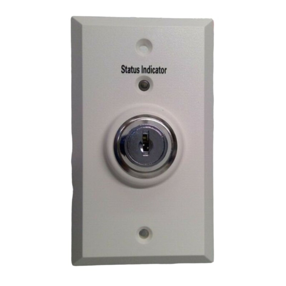
Figure 5
TSM-1X Mounting View
firealarmresources.com
-
Line
Line +
-
Line
Line +
Line 1
Line 2
Line 1
Line 2