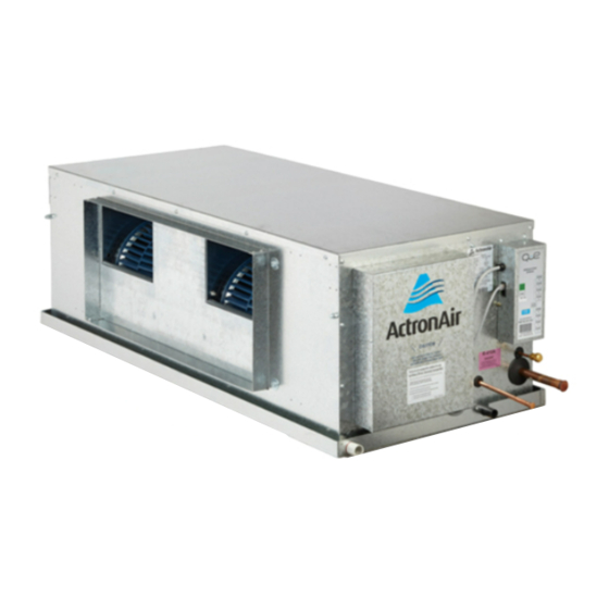
ActronAir ERQ2-14AS Instrukcja instalacji - Strona 8
Przeglądaj online lub pobierz pdf Instrukcja instalacji dla Akcesoria do klimatyzatorów ActronAir ERQ2-14AS. ActronAir ERQ2-14AS 20 stron. Split ducted unit

INSTALLATION INSTRUCTIONS
The installation instructions provided below are intended as a guide only and does not supersede the relevant council,
The installation instructions provided below are intended as a guide only and does not supersede the relevant council,
state and federal codes, regulations and building code standards. Compliance and consultation with the authorities
state and federal codes, regulations and building code standards. Compliance and consultation with the authorities
having jurisdiction with the installation of this equipment is the responsibility of the installer. Actron Air will not be held
having jurisdiction with the installation of this equipment is the responsibility of the installer. Actron Air will not be held
liable for any damages or costs as a result of the installer's failure to comply. Please refer to the matching outdoor unit
liable for any damages or costs as a result of the installer's failure to comply. Please refer to the matching outdoor unit
Installation and Commissioning Guide for further information and details.
Installation and Commissioning Guide for further information and details.
LIFTING THE UNIT
Always observe WH&S regulations for safe and secure lifting
practices in order to prevent physical injury.
Suggested lifting procedures are outlined in the next page as
reference guide to safely lift and transport the unit, however,
these does not over rule the industry WH&S practices.
LOCATION
This unit is intended for indoor installation only. It is highly
recommended that this indoor unit and accessories,
particularly zone barrels, be mounted in the roof cavity.
Mount the unit in a stable and rigid support wherein the
weight is properly distributed, such as roof joist and rafters.
Take into consideration the minimum service access
clearances provided in the unit drawings.
Locate the indoor unit away from the areas where noise is
a critical factor. Use rubber mounting pad (not supplied) in
order to minimize the transfer of noise and vibration into
building structures.
A hanging bracket assembly and rubber grommet (optional
on other units) are also provided to secure the indoor unit
into the roof rafters. This installation configuration is most
suitable for installation that require the unit to be rigidly
secured up from the roof joist.
CONDENSATE and SAFETY TRAY DRAINAGE
An integrated safety drain tray is provided as a standard
inclusion to your indoor unit in order to reduce the potential of
condensate damage to the roof. Drain Kit (optional on some
units) is provided for the condensate drain to be externally
trapped from the indoor unit. Suggested condensate
and safety tray drainage instructions are provided at the
proceeding page for your reference.
SUPPLY AIR and RETURN AIR DUCT
The indoor unit is supplied with duct flange as standard in
order to facilitate the system's duct connection into the unit.
Supply and return air duct works must be adequately sized to
meet the system's air flow and static pressure requirements.
Refer to the unit drawing for supply air and return air duct
dimensions, specific to your requirement.
NOTE: Fit a flexible duct connection in between the unit
and the duct system, where noise and vibration is a critical
consideration.
RETURN AIR FILTER
Air filters must be provided in the return air side of the unit
in order to maintain the efficiency and prolong the operation
Page 8 of 20
of the unit. These are also paramount in order to satisfy
requirement for a clean and hygienic room condition. Air
filters must be placed in an easily accessible location for
service and maintenance.
NOTES:
1. Air filters are not supplied with the unit as individual air
filtration requirements are varied.
2. Ensure that filters are cleaned / replaced regularly.
SUPPLY AIR and RETURN AIR DUCT (OPTIONAL)
Supply Air plenums and Duct Plates (twin-spigot) are
available in order to facilitate your duct system connection to
the indoor unit. The supply air plenums come in 1-way, 2-way
and 3-way options, which offer a wider solutions to your
different air distribution requirements.
SPLIT FAN COIL SYSTEM (OPTIONAL ERQ4-19AS)
The Actron Air innovative 2-piece fan coil system provides
a solution to your difficult and tight roof space installation
requirement. This versatile system has a separate fan and
coil sections. Each of the compact and lightweight section
is simply installed in two separate locations and joined by
flexible duct system. Air ducts are attached to each section
of the split fan coil by both of the supply air plenum and the
twin spigot duct plate.
FAN COIL w/ VERTICAL DISCHARGE (OPTIONAL)
An upright Fan Coil with vertical supply air discharge is
also available wherein installation applications require the
placement of the unit down in a closet, basement or garage.
Please refer to the Technical Catalogue of your indoor unit
for dimensions, installation details and specifications.
FIELD PIPE CONNECTIONS
Specifications and installation requirements for field
pipe connections are contained in the Installation and
Commissioning Guide of the outdoor unit that matches
your indoor unit. Please refer to this guide and thoroughly
understand the procedures for safe and correct indoor and
outdoor connection.
ELECTRICAL FIELD CONNECTION
The power supply and control communication data to the
indoor unit are supplied via the outdoor unit. Please refer
to the wiring diagram supplied with the outdoor unit for
specifications.
All electrical work must be performed by a licensed
electrician and must conform with the wiring diagram and all
relevant electrical authorities.
Installation & Commissioning Guide - ESP Platinum ID Split Ducted Units
Doc. Part No. 0525-052 Rev. 5 200928
